
Build a Lightning Detector
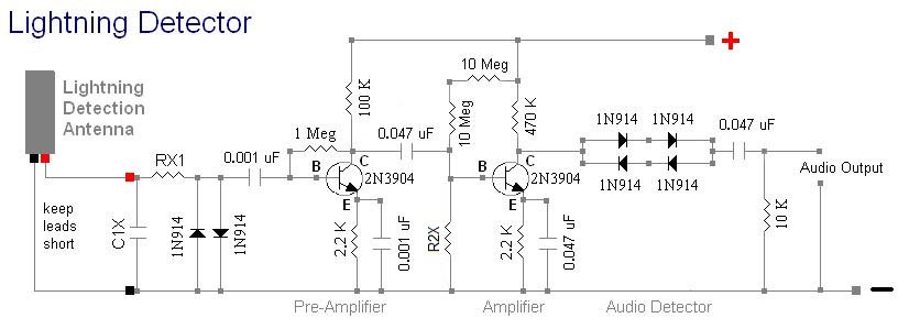
To build the circuit, print the circuit diagram and scale it to a size of approximately 6 1/8 inches long and 2 1/2 inches wide for part fitting. Safety goggles are essential due to the risk of solder splatter. Those unfamiliar with soldering may opt for wire-wrap methods or a solderless breadboard, ensuring a grounded shield base is used to prevent oscillation. Copper-plated weather-strip nails are recommended for securing the diagram to the wood base. Parts should be soldered to the tacks, ensuring no shorts to the ground shield occur except where specified. Transistors should be placed last to avoid static or heat damage, soldering them to the tops of the tacks without excessive bending of leads. The output audio signal exceeds 0.7 volts, sufficient to drive a small audio amplifier loudly, such as Radio Shack's Mini Amp (part number 277-1008C). The antenna should be positioned no more than 10 feet from the receiver and can function effectively indoors, with performance being similar at ground level and elevated positions. The antenna is directional; thus, it should be rotated for optimal reception.An audio amplifier connected to the output will emit loud click sound for each lightning strike detected. When severe storms are approaching, this receiver will go crazy - producing hundreds of clicks per minute.
This is a direct detection amplified "crystal" radio receiver. It does not generate RFI or use regeneration. It has no AGC circuit or no ise-blanker, making it excellent for research applications. Power the detector with a 9 volt battery. It draws little power so it will run for a long time. The Radio Shack audio amplifier will also run a long time (about 2 months) on a 6-volt rechargeable lantern battery. The parts and values are shown on the diagram above on this page. Standard values used. General parts available at any electronics store. Antenna and tuning capacitor available here at RX1 is 1 K ohms. If detection range is too great then use a 10 K-ohm resistor. A variable resistor ( 0 to 50 K-ohms ) can be used to adjust the detection range if desired here. IMPORTANT NOTE: If using antenna D6T-3KC-BC then C1X is 0. 047 uF. This capacitor tunes the antenna to approximately 3 KHz, the lightning detection band center. Check frequency of lightning detector, it should not be lower than 2. 5 KHz or higher than 3. 5 KHz. Adjust capacitor value accordingly if the frequency is out of range. The parts values in circuit design shown were selected for the specific frequency range. IMPORTANT NOTE: If using antenna AF4T-0. 1H-2K-BC-EB then C1X = 100 pF to tune to @ 2. 2 KHz. Do NOT tune below 1. 6 KHz, as this is the ionospheric cut off. Range will be very limited below 1. 6 KHz. R2X is a resistor of 10 meg ohms down to 2 meg ohms. This value controls the sensitivity. Detector will work fine without it, but with an adjustable resistor you can set the range from local to distant.
Without the resistor the range is about 50 to 75 miles. With the resistor the range will be much greater. Resistor should not be less than 2 meg ohms. Try a 5 meg ohms resistor for RX2. How to build it: Print out the above circuit diagram. Scale it down on your printer or photoshop program so that it is the right size, large enough for the electronic parts to fit the dots. This size is about 6 and 1/8th inches long and 2 and 1/2 inches wide. Obtain some safety goggles, you`ll be soldering and hammering nails and cutting a piece of wood (use a hand saw only).
Solder is molten metal and can spatter into your eyes. Do not solder without full eye protection. If you are not familiar with soldering practices, then it -IS- possible to use wire-wrap methods to build the receiver. You can also build the receiver on a solderless breadboard. Ask at Radio Shack store for this item. You`ll need the one with the grounded shield base, receiver -will- oscillate on these if not connected to the shield base.
You will still need the safety goggles when clipping part`s leads or working with the wires. Obtain some copper plated weather-strip nails from the local hardware store. Cut out the paper circuit diagram print-out and tack it to the wood, one tack going into each dot in the diagram. Place the parts on the tacks. Solder parts to the tacks. Make sure tacks do not short to ground shield except where indicated. Place the transistors last after all the other parts have been soldered, to prevent static damage or heat damage.
It is best to just let the transistor sit on top of the tacks and solder it to the top of the tacks with a small drop of solder. Do not bend the transistor`s leads too much. The output audio signal is over 0. 7 volt, enough to drive a small audio amplifier very loudly. Use Radio Shack`s Mini Amp, Radio Shack part number 277-1008C. The antenna should not be placed more than 10 feet away from the receiver. The antenna works indoors and does not need to be high up to work. Try it at ground level then try it up high - not much difference! The antenna is directional so rotate the antenna for bes 🔗 External reference
Related Circuits

This circuit diagram represents a low-cost metal detector utilizing a single transistor circuit in conjunction with an old pocket radio. It operates as a Colpitts oscillator functioning within the medium band frequency range, with the radio tuned to the...
The detector is designed to recognize obstructions at distances ranging from a few millimeters to several centimeters. Similar devices are utilized in industrial and healthcare applications, such as activating a water tap through a magnetic valve. The sensor, IC2,...
This circuit measures the distance covered during a walk. The hardware is housed in a small box that fits into a pocket, and the display operates as follows: the leftmost display, D2 (the most significant digit), shows distances from...
This circuit determines whether multiple inputs in a digital input group are active. It provides a digital measurement of the number of active inputs and allows for the establishment of a threshold for majority-decision applications. This means it can...

An NE555 timer integrated circuit (IC) configured in a specific manner can identify the absence of a pulse or an unusually long duration between two successive pulses in a pulse train. Such circuits are applicable for detecting the intermittent...
Below is the schematic diagram of an audio input module. This module is capable of producing a DC output voltage that is proportional to the amplitude of the input signal. The audio input module typically consists of several key components...