
how to build digital step km counter
This circuit serves as a distance measuring device specifically designed for walking activities. The compact hardware is conveniently stored in a pocket-sized enclosure, facilitating ease of use during walks. The dual display system provides a clear and intuitive readout of distance covered, with D2 indicating kilometers and D1 showing the finer resolution of hundreds of meters. The consistent illumination of the dot on D2 aids in distinguishing between kilometers and hectometers, enhancing user comprehension.
The beeper feature, which can be turned off, offers auditory feedback for every two steps taken, thus allowing users to track their progress without needing to constantly check the display. The choice of a standard step length of approximately 78 centimeters provides a practical basis for distance calculations, with the system designed to trigger the LED indicator after every 64 steps, aligning with the measurement of 50 meters. This design choice emphasizes user engagement and feedback, making the device suitable for casual walkers.
Power management is effectively addressed by requiring user interaction to activate the display, thereby prolonging battery life. The dual button reset mechanism adds a layer of operational safety, preventing accidental resets that could disrupt the tracking process. Although the device does not offer high precision, the accuracy is sufficient for casual use, making it a practical tool for fitness enthusiasts.
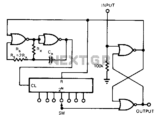
The circuit's functionality is enhanced by the implementation of IC1A and IC1B, which stabilize the signal from the mercury switch, ensuring reliable performance by reducing noise from switch bouncing. The subsequent division of the signal by IC2 and the driving of the displays by IC3 and IC4 ensure that the user receives accurate and timely updates on their walking distance.
The audio feedback generated by IC1C adds an additional layer of user interaction, while the option to disable the sound via SW2 provides flexibility for users in different environments. Overall, this circuit exemplifies a well-thought-out design that balances functionality, usability, and power efficiency, making it a valuable tool for individuals looking to monitor their walking distances effectively.This circuit measures the distance covered during a walk. Hardware is located in a small box slipped in pants` pocket and the display is conceived in the following manner: the leftmost display D2 (the most significant digit) shows 0 to 9 Km. and its dot is always on to separate Km. from hm. The rightmost display D1 (the least significant digit) sh ows hundreds meters and its dot illuminates after every 50 meters of walking. A beeper (excludable), signals each count unit, occurring every two steps. A normal step was calculated to span around 78 centimeters, thus the LED signaling 50 meters illuminates after 64 steps (or 32 operations of the mercury switch), the display indicates 100 meters after 128 steps and so on. For low battery consumption the display illuminates only on request, pushing on P2. Accidental reset of the counters is avoided because to reset the circuit both pushbuttons must be operated together.
Obviously, this is not a precision meter, but its approximation degree was found good for this kind of device. In any case, the most critical thing to do is the correct placement of the mercury switch inside of the box and the setting of its sloping degree.
IC 1A & IC 1B form a monostable multi vibrator providing some degree of freedom from excessive bouncing of the mercury switch. Therefore a clean square pulse enters IC2 that divides by 64. Q2 drives the LED dot-segment of D1 every 32 pulses counted by IC2. Either IC3 & IC4 divide by 10 and drive the displays. P1 resets the counters and P2 enables the displays. IC1C generates an audio frequency square wave that is enabled for a short time at each monostable count.
Q1 drives the piezo sounder and SW2 allows disabling the beep. This circuit is primarily intended for walking purposes. For jogging, further great care must be used with mercury switch placement to avoid undesired counts. 🔗 External reference
Related Circuits
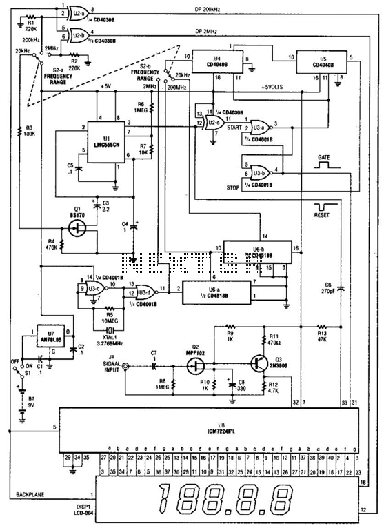
This is a schematic and block diagram of a 2-MHz frequency counter. It utilizes an LSI counter/display driver, an LCD readout, and several logic chips for timebase and timing pulse circuitry. Q2 and Q3 serve as a signal (input)...
High-efficiency step-down switching regulators for positive voltages are common; however, negative step-down switching regulators (negative voltage in, negative voltage out, common ground) are less well known, despite their frequent necessity. Setting them up is not particularly challenging, but literature...
This circuit is constructed using standard components and can be easily adapted for computer control. By utilizing inexpensive surplus transistors and a stepper motor, the overall cost of the circuit can be maintained at under $10. The described circuit is a...
This CMOS circuit functions as a one-shot time delay switch and a general-purpose timer. It comprises a gated oscillator and a latch utilizing a CD4001 quad 2-input NOR gate, along with a CD4020 14-stage counter. The timing interval, TON,...
A wide range frequency meter is a useful tool for an electronics lab. This project describes a frequency meter based on the AT90S231 microcontroller that can measure input frequencies up to 50 MHz. The measured frequency is displayed on...
The ATmega8 microcontroller-based Low-Cost Telemetry Device (LTD) is an efficient telemetry keyer. The LTD measures the voltage levels of up to four analog channels via its on-chip 10-bit ADC, converts the measurements to numbers, and then sends the data...