
Build a Microphone Polarity Tester

In a typical recording studio setup, the correct polarity of the microphone signal is crucial for achieving optimal audio quality. Reversed polarity can lead to phase cancellation, resulting in a thin or hollow sound, particularly when multiple microphones are used simultaneously. This phenomenon occurs because when one microphone's diaphragm moves in response to a sound wave, the corresponding voltage output may be inverted if the wiring is incorrect or if the microphone is connected in reverse.
To ensure proper polarity, an XLR connector's pinout must be understood. The standard configuration for an XLR connector is as follows: Pin 1 is ground (shield), Pin 2 is the positive signal (hot), and Pin 3 is the negative signal (cold). When wiring or troubleshooting, it is essential to verify that the output of the microphone corresponds to this standard. A common method to check polarity is by using an oscilloscope to visualize the waveform. By applying a known sound source, such as a clap or a tone generator, the oscilloscope can display the waveform's phase relationship, allowing for easy identification of any polarity issues.
In addition to the wiring of the microphone, the input stage of the audio interface or mixing console must also be considered. Many modern devices feature a polarity reverse switch, which allows users to quickly correct any phase issues without needing to rewire connections. This feature is particularly useful in complex setups where multiple microphones are used, such as in a drum kit recording.
To mitigate reversed polarity issues, it is advisable to implement a consistent wiring protocol and to educate all personnel involved in the recording process about the importance of microphone polarity. Regular maintenance checks of cables and connectors can also prevent accidental reversals due to wear or damage. Understanding and addressing microphone polarity is essential for achieving high-quality recordings and ensuring that sound sources are accurately captured in the studio environment.Many things can go wrong in a modern recording studio, but few are as difficult to track down as reversed microphone polarity. When a microphone is placed in front of a sound source, a positive pressure on its diaphragm caused by forward-moving air results in a positive voltage on one of its output pins and a negative voltage on the other.
But which pin is positive? These days most microphones have XLR output connectors, with Pin 2 used for the positive voltage output and Pin 3 for the negative. 🔗 External reference
Related Circuits
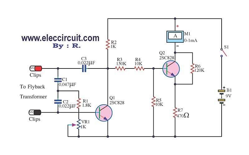
The circuit tests a flyback transformer used in televisions, and it is simple, easy, and inexpensive to construct. A friend who is a TV repairman provided this information. The circuit designed for testing a flyback transformer is essential for diagnosing...
This compact Infrared Remote Control Tester circuit is designed to verify the functionality of an infrared remote control unit. The circuit operates by connecting a piezo buzzer directly to an IR receiver integrated circuit (IC). The TSOP1738 integrated IR...
Dynamic microphones utilize a moving coil within a magnetic field to convert mechanical movements into electrical signals. An ordinary mini speaker can be transformed into a... Dynamic microphones operate on the principle of electromagnetic induction. When sound waves hit the diaphragm...
I designed a simple sinewave generator based on a Analog Devices AD9832 chip. It will generate a sinewave from 0.005 to 12 MHz in 0.005 Hz steps. That's pretty good, and definitely good enough for me! But while waiting...
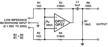
A simple but effective fixed gain transformerless microphone preamplifier circuit diagram is shown in the picture below. The circuit amplifies differential signals from low impedance microphones by 50 dB and has an input impedance of 2 kOhms. The OP27/37...
A homebrew 2M transceiver was designed for mobile use, eliminating the need for a fist microphone. A low-cost personal hands-free kit for mobile phones was initially considered, but it resulted in inadequate audio performance. The circuit utilized had a...