
Infrared Remote Control Tester
The Infrared Remote Control Tester circuit consists of several key components that work together to provide an effective testing solution for infrared remote controls. At the heart of the circuit is the TSOP1738 IR receiver, which is designed to detect infrared signals modulated at a specific carrier frequency, typically around 38 kHz. When an infrared signal from the remote control is received, the TSOP1738 demodulates the signal and outputs a square wave at approximately 700 Hz, which corresponds to the modulation frequency of the incoming signal.
The piezo buzzer serves as an output device that converts the electrical signal from the TSOP1738 into audible sound. When the IR signal is detected, the buzzer emits a tone, indicating that the remote control is operational. The circuit is powered by a 9 V battery, which is regulated down to 5 V using a voltage regulator circuit. This ensures that the TSOP1738 and the piezo buzzer receive the appropriate voltage for optimal operation.
In terms of component selection, while the TSOP1738 is a popular choice, other IR receiver ICs can be substituted as long as they are compatible with the modulation frequency of the remote control being tested. This flexibility allows for a broader range of applications, accommodating various remote controls that may operate at different frequencies.
The circuit design is relatively straightforward, making it accessible for hobbyists and professionals alike. It is essential to ensure proper connections and component placement on the PCB or breadboard to avoid any operational issues. Overall, this Infrared Remote Control Tester is a valuable tool for confirming the functionality of remote control units, providing a simple yet effective means of troubleshooting infrared communication devices.This small InfraRed Remote Control Tester circuit is used for checking the operation of an infrared remote control unit. The circuit is based on the idea of connecting a piezo buzzer directly to an IR receiver IC. The TSOP1738 integrated IR receiver accepts, amplifies and demodulates the IR signal from the remote control, producing an output with
a frequency of around 700 Hz. The piezo buzzer is connected to its output, rendering the signal audible. All the other components are simply concerned with producing a stable 5 V power supply from the 9 V PP3-(6F22) type battery. Instead of the TSOP1738 similar devices from other manufacturers can be used, and of course carrier frequencies other than 38 kHz can be used.
The circuit still works if there is a mismatch between the nominal carrier frequencies of the transmitter and receiver IC, but range is reduced. It is still, however, adequate for determining whether a remote control is producing an IR signal or not.
🔗 External reference
Related Circuits

This circuit can power on or off various electric and electronic devices such as ADSL modems, personal computers, water boilers, water pumps, garage doors, lights, and more. Additionally, it allows for monitoring the status of eight switches, which can...
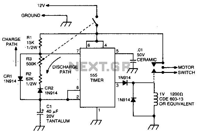
This circuit utilizes the 555 timer in astable or oscillatory mode. The duration for which the timer remains off is determined by the values of capacitor C1, resistor R2, and resistor R3. A potentiometer is incorporated to adjust the...
The FM497 is an integrated electronic ignition controller designed for breakerless ignition systems that utilize Hall effect sensors. This device operates an external NPN Darlington transistor to manage the coil current, thereby delivering the necessary stored energy while maintaining...

The following method allows the timer to be triggered by a normally closed switch. This would be useful in applications such as intrusion alarms where the protection circuit is broken if a window or door is opened. Trigger Input...

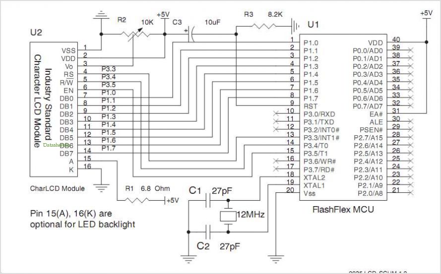
PICLink RS232 low-cost development controller with ADC. The PICLink RS232 embedded controller module provides any microcontroller with RS232 communication capabilities. The PICLink RS232 embedded controller is designed to facilitate communication between microcontrollers and RS232 devices, making it an essential component...
This voltage-controlled oscillator circuit is compact and exhibits good linearity. The precision can be better than 0.01% if properly constructed. The circuit provides three different output waveforms: square, triangle, and sawtooth, which are essential for music synthesizers and measurement...
Warning: include(partials/cookie-banner.php): Failed to open stream: Permission denied in /var/www/html/nextgr/view-circuit.php on line 713
Warning: include(): Failed opening 'partials/cookie-banner.php' for inclusion (include_path='.:/usr/share/php') in /var/www/html/nextgr/view-circuit.php on line 713