
Build a USB Powered AA NiMH and NiCd Battery Charger
The design of this charger integrates several critical electronic components to ensure efficient charging and safety. The LM393 comparator serves as a temperature monitoring and control mechanism, while the thermistor provides real-time feedback on the temperature of the cells being charged. The use of a voltage divider formed by R3 and TR1 allows for precise voltage regulation based on temperature, which is essential for preventing overheating and potential damage to the cells. The charging current is carefully managed through the transistor Q1, which acts as a switch to control the flow of current based on the comparator's output. The overall design emphasizes efficiency and safety, making it suitable for charging NiMH and NiCd cells while minimizing the risk of overcharging or overheating. This project exemplifies a practical application of electronic components in creating a user-friendly and efficient battery charging solution.This project, which can charge a pair of AA Nickel Metal Hydride (NiMH) or Nickel Cadmium (NiCd) cells using a laptop`s USB port for power, arose to address part of that problem. (By the way, if you want to lighten your laptop load, take a look at the MoGo Mouse. ) Any USB port can supply 5V at up to 500mA. The USB standard specifies that a device may not use more than 100mA until it has negotiated the right to use 500mA,
but apparently no USB ports enforce that requirement. This makes the USB port a convenient source of power for devices such as this charger. The USBCell is a 1300mAh AA NiMH cell with a removable top that allows it to be plugged directly into a USB port. No separate charger is needed. Unfortunately, the cell capacity is very low (most NiMH AA cells are 2500mAh these days), and each cell requires its own port.
There is a two cell USB powered AA charger available, sold under a variety of names, but it charges at a very low 100mA rate. The distributor calls it an overnight charger , but at 100mA, a 2500mA cell would take about 40 hours to charge (40 instead of 25 due to the inefficiencies of charging at low currents).
I found a 2/4 cell charger that can be powered by a USB port, auto adapter, or wall wart, but it is as large as the wall charger I`m trying to replace. Different ones can be found here and here, but these take 10 to 12 hours to charge 2500mAh cells. [December 2007 Update: Sanyo has introduced a USB powered charger for their Eneloop batteries. This charger has none of the drawbacks listed above, and will charge a pair of 2000mAh cells in about 5 hours, or a single cell in half that time.
Although designed for Eneloops (see my review ), it will work with regular NiMH cells as well. Watch for a review on this site soon. ] The charger in this project is designed to charge two AA NiMH or NiCd cells of any capacity (as long as they are the same) at about 470mA. It will charge 700mAh NiCds in about 1. 5 hours, 1500mAh NiMHs in about 3. 5 hours, and 2500mAh NiMHs in about 5. 5 hours. The charger incorporates an automatic charge cut-off circuit based on cell temperature, and the cells can be left in the charger indefinitely after cut-off.
The heart of this charger is Z1a, one half of an LM393 dual voltage comparator. The output (pin 1) can be in one of two states, floating or low. While charging, the output is pulled low by an internal transistor, drawing about 5. 2mA of current through Q1 and R5. Q1 has a beta of about 90, so about 470mA will flow through into the two AA cells being charged. This will fully charge a pair of 2500mAh cells in just over 5 hours. TR1 is a thermistor that is in direct contact with the cells being charged. It has a resistance of 10k © at 25 °C (77 °F), which varies inversely with temperature by about 3. 7% for every 1C ° (1. 8F °). R3 and TR1 form a voltage divider whose value is applied to the inverting input (pin 2, Vtmp). At a temperature of 20 °C (68 °F), TR1 is about 12k ©, which makes Vtmp about 1. 76V. Once the cells are fully charged, the charge current will literally go to waste, in the form of heat. As the cell temperature rises, TR1 ²s resistance drops. At 33 °C (91 °F), the resistance will be about 7. 4k ©, which makes Vtmp about 1. 26V, which equals the Vref voltage. As the temperature rises above 33 °C, Vtmp will become less than Vref, and the open-collector output of Z1a will float high.
Therefore, the current flowing through R5 is greatly reduced, as it is now limited by R1, R2, and R4. As a result, the current flowing through Q1 and the cells is reduced to a 10mA trickle charge rate. Also, because R4 is now connected to +5V through R5 and Q1 instead of being held at 0. 26V by Z1a, the Vref voltage changes to about 2. 37V. This guarantees that as the cell temperature drops, the charger won`t tu 🔗 External reference
Related Circuits
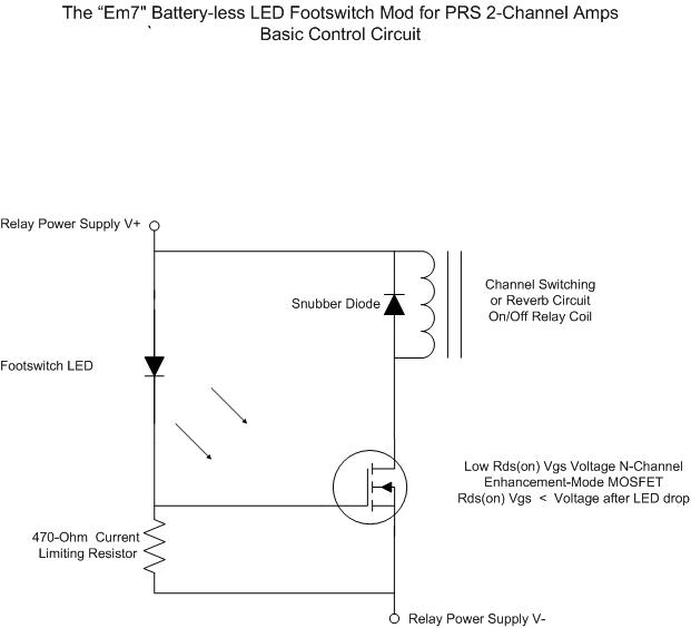
For individuals seeking LED-based footswitching without the inconvenience of battery installation, a battery-less LED-based footswitch modification is being developed for 2-channel amplifiers. This solution is designed to work with the existing TRS jack and footswitch, and it will involve...
Most peripherals that interface with a PC utilize a USB port. The computer's power supply circuit, specifically the switched-mode power supply (SMPS), is designed to provide constant power to all internal components. However, when external peripherals that require a...
This flasher operates from a 12-volt car or boat battery. It provides an output of 36 to 40 watts, with a variable flash rate of up to 60 flashes per minute. The device features independent control of both on...

The circuit for the Digital Tachometer/RPM Counter consists of a few components. They should be connected according to the provided circuit diagram. The PIC used is on a demonstration board, meaning the clock, power, and ground pins are already...
Alkaline Battery Charger. This circuit was specifically designed to recharge alkaline cells. The unusual connection of the transistor in each charging unit will cause it to oscillate. The alkaline battery charger circuit is engineered to effectively recharge alkaline batteries, which...
BattMan II is a computer-controlled battery manager designed for typical rechargeable batteries utilized by R/C and electronics hobbyists, as well as various consumer product batteries. BattMan II supports Nickel-Cadmium (NiCd), Nickel-Metal-Hydride (NiMH), Lithium-Ion (Li-Ion), Lithium-Polymer (LiPo), Lithium-Nano-Phosphate (LiNP), and...
Warning: include(partials/cookie-banner.php): Failed to open stream: Permission denied in /var/www/html/nextgr/view-circuit.php on line 713
Warning: include(): Failed opening 'partials/cookie-banner.php' for inclusion (include_path='.:/usr/share/php') in /var/www/html/nextgr/view-circuit.php on line 713