
High-power battery-operated flasher
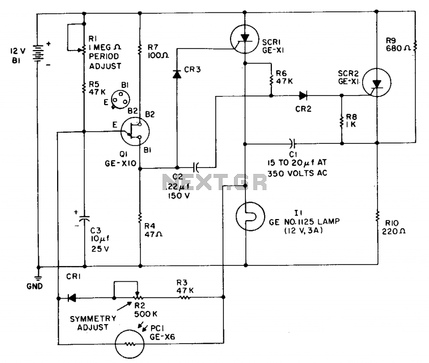
The flip-flop timing is regulated by a conventional UJT (Unijunction Transistor) oscillator configuration, which includes components such as Q1, R1, and C3. Potentiometer R2 and diode CR1 ensure independence in on/off timing. A photoconductor, designated as PC1, disables the UJT firing circuit during daylight hours.
This flasher circuit is designed for efficient operation in automotive and marine environments, utilizing a 12-volt power supply. The output power range of 36 to 40 watts is suitable for various lighting applications, ensuring visibility in low-light conditions. The variable flash rate feature allows customization based on user preference or regulatory requirements, with a maximum frequency of 60 flashes per minute.
The core of the flasher's functionality lies in its flip-flop mechanism, constructed using silicon-controlled rectifiers (SCRs). SCR1 and SCR2 alternate the current flow to the load, creating the flashing effect. The design allows for one SCR to control the lamp load while the other remains grounded, which is critical in applications where a negative potential is required.
The timing of the flashing is managed by a UJT oscillator, which provides a stable pulse output. The inclusion of resistors (R1) and capacitors (C3) determines the frequency and duration of the flashes. Potentiometer R2 offers a means to adjust the timing characteristics, allowing for fine-tuning of the on and off cycles to meet specific operational needs. Diode CR1 plays a crucial role in ensuring that the timing of the flashes is independent of the photoconductor's operation.
The photoconductor (PC1) is a vital component that enhances the automatic functionality of the flasher. It senses ambient light levels, effectively locking out the UJT firing circuit during daylight hours to prevent unnecessary activation of the flasher. This feature not only conserves energy but also extends the lifespan of the flasher by reducing wear during daylight conditions.
Overall, this flasher circuit design is a robust solution for applications requiring reliable and efficient flashing signals, combining advanced timing control with automatic day/night operation.This flasher operates from a 12-volt car or boat battery. It offers 36 to 40-watts output, variable flash rate (up to 60 flashes per minute), independent control of both on and off cycles and photoelectric night and day control that turns the flasher on at night and shuts it off during the day for automatic operation. SCR1 and SCR2 form a basic dc flip-flop. The lamp load is the cathode leg of one SCR so that the other side of the load may be at ground (negative) potential (required in some applications).
The flip-flop timing is controlled by a conventional UJT oscillator arrangement (Ql, Rl, C3, etc.). Potentiometer R2 and diode CR1 provide on/off timing independence. Photoconductor PCI locks out the UJT firing circuit during the daylight hours. 🔗 External reference
Related Circuits

This circuit utilizes a voltage-doubler power supply to charge a 60 µF capacitor, which is subsequently discharged through a Xenon lamp. The SIDAC device, manufactured by Motorola, is a two-terminal component that triggers at a predetermined voltage level. The...
This circuit functions as a phone message flasher, providing an alternative method to alert users of an incoming call. When the phone rings, a high line voltage is activated. The phone message flasher circuit is designed to enhance the traditional...
The concept of this economical flashing LED indicator is straightforward. It employs a low-frequency oscillator to drive two LEDs connected in anti-parallel. In the circuit diagram, it can be observed that the current flows for a brief duration with...
When the preset is set to its maximum, the LED flashes approximately every half second. This flashing rate can be increased by using a larger capacitor value, for instance, changing from 10µF to 22µF will result in a flashing...
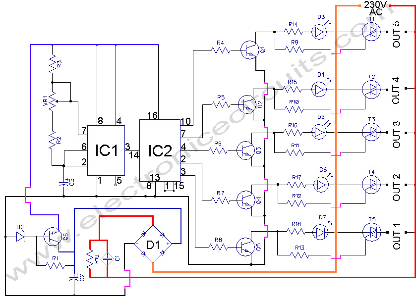
5 WAY AC FLASHER. These types of circuits are commonly used in various ceremonies such as the Wesak festival, Christmas, and weddings. This 5 WAY AC FLASHER circuit. The 5 Way AC Flasher circuit is designed to produce a sequential...
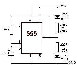
This LED flasher circuit utilizes a 555 timer integrated circuit (IC). The circuit diagram is straightforward and requires only a few external components. When operational, the red LEDs will flash sequentially at a predetermined frequency, similar to the indicators...