
Build A Digital Tachometer/RPM Counter Circuit

The Digital Tachometer/RPM Counter circuit is designed to measure the rotational speed of a shaft or wheel and display the results on a standard 16x2 character LCD. The core of this circuit is a microcontroller, specifically a PIC microcontroller, which processes the input signals and manages the output to the LCD.
The circuit operates by generating +5V pulses that are sent to the RC2/CCP1 pin of the PIC, where the capture module #1 is located. These pulses correspond to the number of rotations per minute (RPM) of the monitored object. The PIC is programmed to count these pulses over a specific time interval, allowing it to calculate the RPM based on the frequency of the incoming pulses.
The LCD interfacing consists of an 8-bit data bus along with 3 control signals: Register Select (RS), Read/Write (R/W), and Enable (E). The PIC sends commands and data to the LCD through these lines, controlling what is displayed. The power, ground, and contrast adjustments are crucial for proper LCD operation, ensuring that the display is clear and readable.
The HD44780 controller is prevalent in many LCD applications and is well-documented, making it easier to implement and troubleshoot. The datasheet provides detailed information on the command set, timing diagrams, and electrical characteristics, enabling efficient integration into the tachometer circuit. This design allows for real-time monitoring of RPM, making it a valuable tool for various engineering applications.The circuit for the Digital Tachometer/RPM Counter tutorial consists of only a few devices. Wire them up according to the following circuit diagram. The PIC I`m using is on a demonstration board, which means the clock, power and ground pins are already wired up so I didn`t bother to include that on the schematic. This is the digital tachometer po rtion of circuit that will send +5v pulses to the RC2/CCP1 pin of the pic. The CCP module, specifically the capture module #1 on the PIC is located at this pin. This is the standard 16x2 character LCD and the interface consists of 8 bits of data, with 3 control signals. Power, Ground and Contrast are the last signals to wire up. The PIC sends commands to this 16x2 LCD over the control and data lines and the LCD does what it is told.
The HD44780 system that this LCD uses is standarized and the datasheet is widely available. 🔗 External reference
Related Circuits
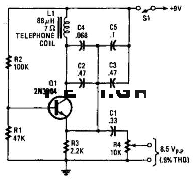
An 88 mH surplus telephone toroidal coil is utilized in a 1 kHz oscillator. It can provide up to 8 V peak-to-peak into a high-impedance load. The total harmonic distortion (THD) is 0.9%. The circuit employs an 88 mH toroidal...
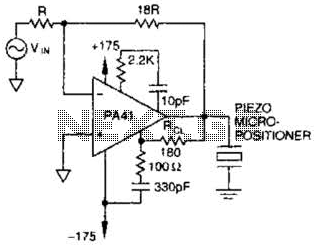
The PA41 from Apex Microtechnology is utilized to drive a piezoelectric micropositioner. The drive voltage is less than 20 V peak-to-peak at the input. The PA41 is a high-performance power amplifier designed specifically for driving piezoelectric devices, which require precise...
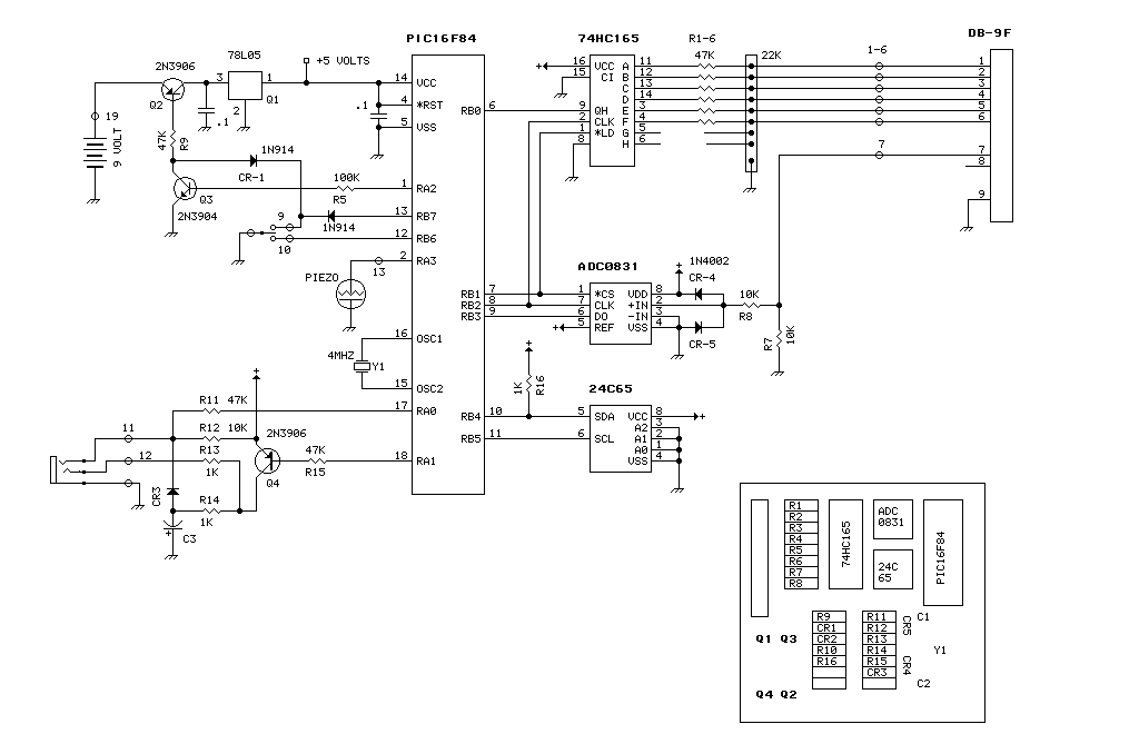
Intermittent failures in electronic systems are some of the most difficult to diagnose. This device is designed to run for days at a time looking for a failure and logging the event. The unit is based on a PIC16F84....
Unlike most surface-mounted device (SMD) resistors, SMD ceramic capacitors do not have their values marked. To determine the value of these capacitors, a capacitance meter is required. SMD ceramic capacitors are widely used in modern electronic circuits due to their...
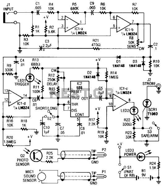
Sound or light sensors connected to J2 produce a voltage that is amplified by IC1-a and IC1-b. A positive trigger voltage developed by D1 and R3, and amplified by IC1-d, drives IC2 and IC1 to trigger SCR1. SCR1 is...
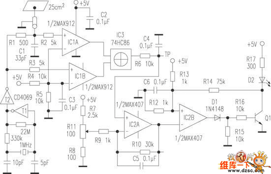
The human approach detector circuit consists of an integrated operational amplifier, a gate circuit, and a resistor-capacitor unit as illustrated in the diagram. The 1 MHz oscillator is composed of a reverser T1, a 1 MHz crystal oscillator, and...