
USB Power Booster Circuit PCB
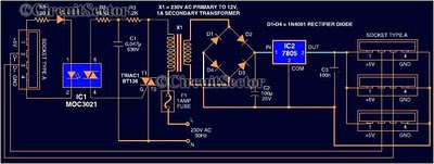
The described USB power booster circuit is crucial for maintaining the stability of computer systems when multiple high-power external devices are connected. The circuit begins with the MOC3021, which acts as an optoisolator, allowing for safe control of the triac without direct electrical connection to the high-voltage side. The MOC3021 is triggered by a control signal, enabling it to conduct and activate the BT136 triac. The BT136, a type of triac, allows current to flow in both directions, effectively controlling the power delivered to the load, which in this case is the transformer.
The transformer steps up the voltage as necessary and provides isolation between the high-voltage AC mains and the low-voltage USB output. The output from the transformer is then rectified, typically using a bridge rectifier, to convert the AC voltage into a usable DC voltage. The IC 7805 voltage regulator is integrated into the circuit to maintain a stable 5V output, which is essential for the proper functioning of USB peripherals. The regulator ensures that fluctuations in input voltage or load do not affect the output voltage, thus providing reliable power to connected devices.
Overall, this USB power booster circuit is designed to enhance the power delivery capabilities of a standard USB port, allowing for the connection of multiple high-power devices without compromising the stability of the PC. The combination of the opto-diac, triac, transformer, and voltage regulator creates a robust solution for users requiring additional power for their USB peripherals.Most of the peripherals that interface with PC uses USB port. The computers power supply circuit of SMPS will be designed to maintain constant power to all computer parts only. however we connect external peripherals to PC that requires significantly large power, USB power shortage will occur result in a instability of PC.
when too many devices ar e connected simultaneously, there is a possibility of power shortage. Therefore an external usb power amplifier or source has to be added to power the external devices. This circuit is of USB power booster designed to feed power to USB type A socket. To increase power to usb, we use an MOC3021 which is an opto-diac which triggers, BT 136 which is a triac which result in a available power boosting through transformer. We know that IC 7805 is a 5v voltage regulator which regulates the output to give constant voltage to usb peripherals.
🔗 External reference
Related Circuits
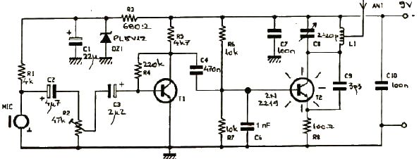
This FM transmitter electronic project operates in the FM band with a transmission power of approximately 250 mW. The circuit is straightforward and utilizes common transistors and electronic components. The T1 transistor, which may be a BC107, BC171, or...

The interface circuit is placed between the computer's standard video signal output terminal and the television. It amplifies the standard 1V (Peak-to-Peak) video signal to 3V (Peak-to-Peak). The negative feedback circuit consists of transistors T1 and T2, providing a...
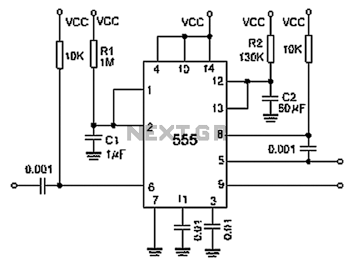
A 0.001 F coupling capacitor connects the output of the first half of a 556 timer to the input of the second half, providing an individual delay that equals the total delay. The 6-foot ground can immediately activate the...
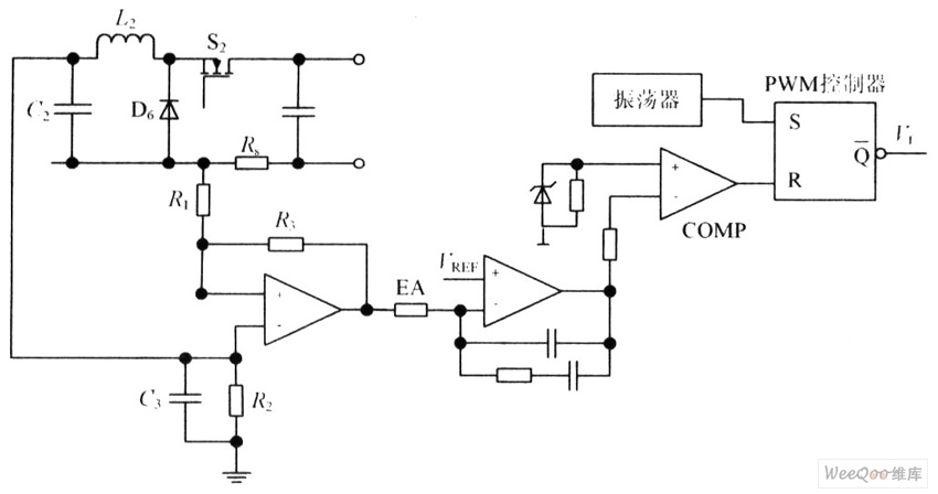
The circuit is capable of enhancing the system power factor to a value exceeding 0.99. It effectively reduces the waveform distortion of the input supply current, ensuring compliance with GB15144 standards, with a distortion index lower than level L....
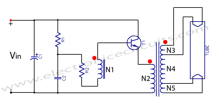
Fluorescent tube light circuit of an inverter that uses a single transistor and a single transformer. This type of inverter can be made in various configurations. The fluorescent tube light circuit described utilizes a basic inverter design that incorporates a...
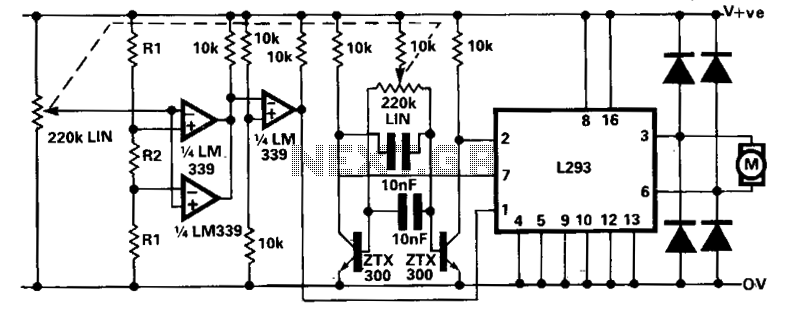
A limitation of the bi-directional proportional motor control circuit is that when the potentiometer is in its center position, the motor does not stop but continues to creep. This occurs due to the challenge of precisely adjusting the potentiometer...
Warning: include(partials/cookie-banner.php): Failed to open stream: Permission denied in /var/www/html/nextgr/view-circuit.php on line 713
Warning: include(): Failed opening 'partials/cookie-banner.php' for inclusion (include_path='.:/usr/share/php') in /var/www/html/nextgr/view-circuit.php on line 713