
Build an Experimenters Power Supply
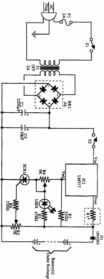
The described circuit is a robust power supply solution suitable for various electronic applications. The use of a 12.6-volt transformer ensures adequate voltage for the voltage regulators while allowing for a sufficient overhead to maintain stable output voltage under varying load conditions. The inclusion of a bridge rectifier allows for efficient conversion of AC to DC, and the use of filtering capacitors minimizes ripple, enhancing the quality of the output voltage. The design also incorporates safety features such as fuses and switches, ensuring that the circuit can be safely powered on and off. The voltage regulators chosen for this design (7805 and 7812) are well-regarded for their reliability and ease of use, making them ideal for hobbyist and professional applications alike. The multi-voltage capability of the design allows it to serve a wide range of devices, making it a versatile addition to any electronics lab or project. The careful consideration of component ratings and configurations ensures that the power supply will operate efficiently and reliably, providing a stable source of power for various electronic circuits.Note the incoming ac routed to the primary terminals on a 12. 6-volt transformer. The hot side of the ac is connected through a fuse and a single-pole single-throw (SPST) toggle switch. With the switch in the OFF (open) position, the transformer receives no power so the supply is off. The 117 VAC is stepped down to about 12. 6 volts. The transformer specified here is rated at 2 amps, sufficient for the task at hand. Remember that the power supply is limited to delivering the capacity of the transformer (and later, the voltage regulator). A bridge rectifier, BR1, converts the ac to dc (shown schematically in the dotted box). You can also construct the rectifier using discrete diodes (connect them as shown within the box). When using the bridge rectifier, be sure to connect the leads to the proper terminals. The two terminals marked with a ” connect to the transformer. The + and ” terminals are the output and must connect as shown in the schematic. A 5-volt, 1-amp regulator, a 7805, is used to maintain the voltage output at a steady 5 volts. Note that the transformer supplies a great deal more voltage than is necessary. This is for two reasons. First, lower-voltage 6. 3- or 9-volt transformers are available, but most don`t deliver more than 0. 5 amp. It is far easier to find 12- or 15-volt transformers that deliver sufficient power. Second, the regulator requires a few extra volts as overhead to operate properly. The 12. 6-volt transformer specified here delivers the minimum voltage requirement, and then some. Capacitors C1 and C2 filter the ripple inherent in the rectified dc at the outputs of the bridge rectifier.
With the capacitors installed as shown (note the polarity), the ripple at the output of the power supply is negligible. LED1 and R1 form a simple indicator. The LED glows when the power supply is on. Remember the 270-ohm resistor; the LED will burn up without it. The output terminals are insulated binding posts. Don`t leave the output wires bare, or they could accidentally touch one another and short the supply.
Solder the output wires to the lug on the binding posts, and attach the posts to the front of the power supply chassis. The posts accept bare wires, alligator clips, or even banana plugs. The 5- and 12-volt versions of the power supply are basically the same, but with a few important changes.
Refer again to ill. 12-2. First, the transformer is rated for 18 volts at 2 amps. The 18-volt output is more than enough for the overhead required by the 12-volt regulator and is commonly available. You may use a transformer rated at between 15 and 25 volts. The regulator, a 7812, is the same as the 7805 except that it puts out a regulated + 12 volts instead of + 5 volts.
Use the T series regulator (TO-220 case) for low-current applications and the K series (TO-3) for higher capacity applications. Lastly, R1 is increased to 330 ohms. The multi-voltage power supply is like four power supplies in one. Rather than using four bulky transformers, however, this circuit uses just one, tapping the voltage at the proper locations to operate the +5, +12, -5, and -12 regulators.
The circuit, as shown in ill. 12-3, is composed of two halves. One half of the sup ply provides +12 and ”12 volts; the other half provides + 5 and ”5 volts. Each side is connected to a common transformer, fuse, switch, and wall plug. See TABLE 12-3 for a parts list. The basic difference between the multi-voltage supply and the single-voltage supplies described earlier in this section is the addition of negative power regulators. Circuit ground is the center tap of the transformer. Make two boards, one for each section. That is, one board will be the ± 5-volt regulators and the other board will contain the ± 12-volt regulators.
The supply provides approximately 1 amp for each of the outputs. Use nylon binding posts for the five outputs (ground, +5, +12, - 🔗 External reference
Related Circuits
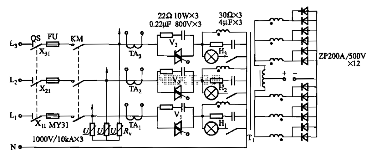
A 1500A-7V phase thyristor power regulator circuit is designed for plating applications. It consists of three major components: the main circuit, the control circuit, and the protection circuit. The control circuit includes a trigger circuit, a synchronous power supply,...
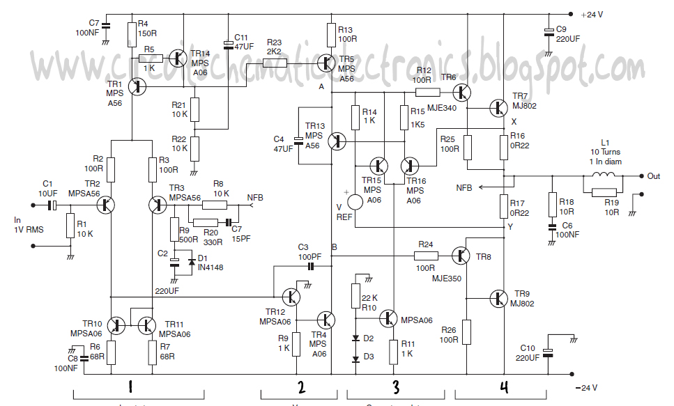
This design schematic represents a Class A power amplifier. It closely matches the operating parameters of Class B to facilitate comparison, particularly with a negative feedback (NFB) factor of 30dB at 20 kHz. The front end is similar to...
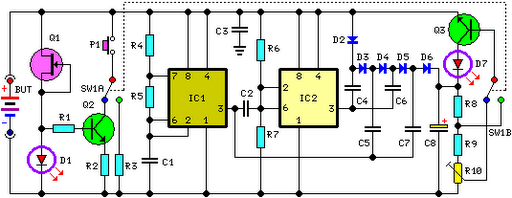
FET Q1 functions as a constant current generator, providing biasing for LED D1 and the base of Q2. This configuration ensures that D1 emits light at a consistent intensity, regardless of the battery voltage, which ranges from 3 to...
The programmable power supply is a component of an integrated test system for guided missiles, designed to provide and test various required stabilized direct current voltage supplies for guided missiles. It features real-time monitoring, overvoltage protection, and automatic overload...
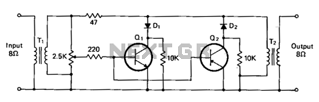
T1 and T2 are 600 to 8-ohm transformers (any transistor radio output transformers with 500 to 4-ohm impedance may be used). Q1 is a 2N2222 NPN transistor, and Q2 is a 2N2907 PNP transistor. D1 and D2 are 1N270...
This is an efficient 4-stage stabilized power supply unit designed for testing electronic circuits. It delivers well-regulated and stabilized output, which is crucial for most electronic circuits to function correctly. The circuit includes an audio-visual indicator that activates in...