
Programmable power supply design study of the integrated test system of guided missile

The programmable power supply serves as a vital component within the guided missile testing infrastructure, ensuring that various voltage levels are accurately generated and monitored to meet the stringent requirements of missile systems. The integration of advanced control mechanisms, such as PWM and real-time monitoring through an industrial computer, enhances the reliability and functionality of the power supply. The careful selection of components, including high-capacity electrolytic capacitors and robust switching elements, contributes to the overall stability and efficiency of the power supply, enabling it to handle varying loads and conditions while maintaining precise output voltages. This design not only facilitates the testing of missile systems but also ensures that safety mechanisms are in place to protect both the equipment and the operator from potential hazards associated with overvoltage and excessive load conditions.The programmable power supply is the association of one of the integrated test system of guided missile, are used for offering and testing various required direct-flow stabilized voltage supply of guided missile, in addition have functions such as monitoring, overvoltage, excessive load automatic protection, etc. in real time of output voltage. Thi s association is made up of eight pieces of breadboard inserted on the standard 100 mother strip, including 40V/- 43V power panel, 24V continuously adjustable power panel, 20V/ 22V power panel, 20V power panel, 5V/- 80V power panel, power measure and last board, before keyset and behind make up keyset. The functional block diagram of programmable power supply is shown as in Fig. 1, the industrial computer switches over the output voltage of the power through PCL812PG data collecting card figure I/O passway, utilize D/A to output the comparative voltage which regulates PWM in order to control the continuous change of output voltage, monitor the output of the power in real time through A/D passway.
1 The input 30V after voltage transformer of the city power of the incoming circuit 220V/50Hz is exchanged, sends into the switching circuit after full-wave rectification and electrolytic capacitor E2, E3 are filtered. E2, E3 fetch 2200 F, it uses ESR value of reducing the Filtering capacitance in parallel. 2 Adopt the switch stabilized voltage supply of the series type in the circuit design of the switching circuit, the pulse width modulator is SG3524, power switching element is 2N6277, the circuit sets up protective circuit of pressure flow, as the power supply is pressed, at the time of the excessive load, the direct current of the automatic key-out is input, thus the purpose to achieve protective circuit.
The operating frequency of the switching circuit is: 3 The output circuit is made up the smoothing circuit by inductor L1 and electrolytic capacitor E5, E8, R5 is the artificial load. The choice of the Filtering capacitance of the output is very important, output ripple and output current requirement in order to meet minimumly, capacitive ESRmax = Vout / Iout, Vout is a ripple range, Iout is 1/4 of the electric current designing requirement, for this reason, E8 chooses the CD28 type tetrapolar electric capacity, can satisfy 5A Tap, the ripple is smaller than the designing requirement of 10mV.
The programmable power supply, under the control of industrial computer, according to the difference of measurands, switch over and the measurand emerges the required mains voltage, and can make to the programmable power supply up and carry on self test and monitor through the industrial computer. Because 20V/ 22V two kinds of power phase difference are minor, utilize body circuit of the same power, change the output of the power through switching over different reference voltage.
The circuit still changes the comparative reference voltage of the power through the control code P2 of the industrial computer, reach the same circuit and output two pieces of different voltage 20V and 22V Purpose. The control code P0 is used in order to control width modulated pulsingly and export, thus the controlled switch stabilized voltage supply is the work.
When P2 is the high level, OC2 does not turn on, adjusts W4 to 1. 76k, output voltage Vout = =22V; When P2 is the low level, OC2 turns on, W3, R23, R21, R20 connect in parallel, it can have W3 R23 to calculate =2. 4* R21 R20 =17. 52k, it is 20V that can get the output voltage to adjust W3 to about 3. 5k. The programmable power supply is the association of one of the integrated test system of guided missile, are used for offering and testing various required direct-flow stabilized voltage supply of guided missile, in addition have functions such as monitoring, overvoltage, excessive load automatic protection, etc.
in real time of output voltage. This association is made up of eight pieces of breadbo 🔗 External reference
Related Circuits
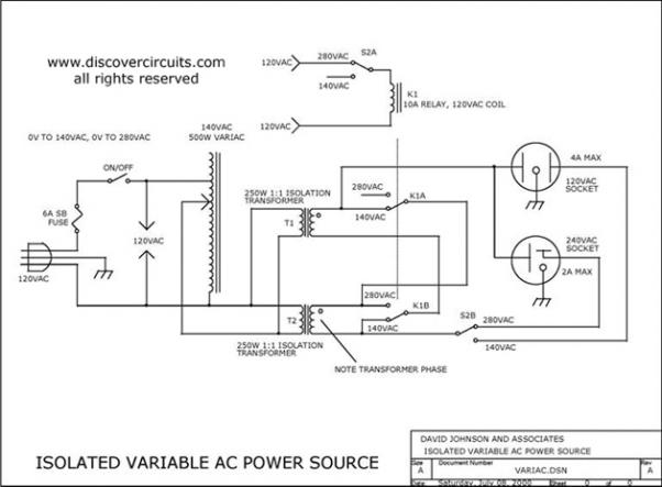
Variable AC Power Supply Circuit. In electronics, it is often useful to have a fully isolated variable AC power supply. With such a device, one can safely test various AC-powered circuits. A variable AC power supply circuit is an essential...
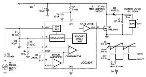
A temperature-controlled pulse-width-modulator (PWM) boost converter circuit diagram is illustrated in the following figure. This boost converter is designed to operate a 12V fan using a 5V supply while maintaining temperature control. The temperature-controlled PWM boost converter circuit operates by...

The circuit depicted in the figure comprises a PGA103 programmable gain instrumentation amplifier. This design utilizes the PGA205 and PGA103 in a cascading configuration, resulting in a total gain for the amplifier. The gain is determined by the product...
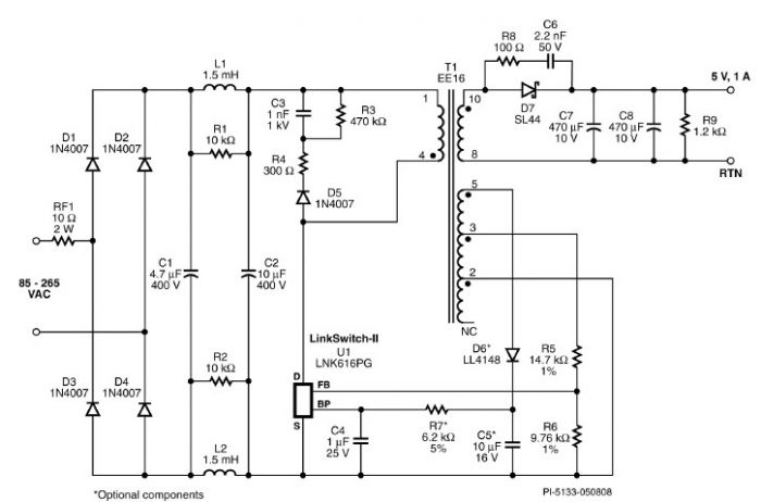
A very simple 5-volt constant voltage, constant current (CV/CC) universal-input power supply for cell phone or similar charger applications can be designed using the LNK616PG product from the LinkSwitch-II family. This low-cost charger adapter accepts a wide range of...

This circuit is just an implementation of the 7805 integrated voltage regulator. What this little component does is to lower a voltage and stabilize it by reducing noise and ripple, in order for circuits to have the constant voltage...
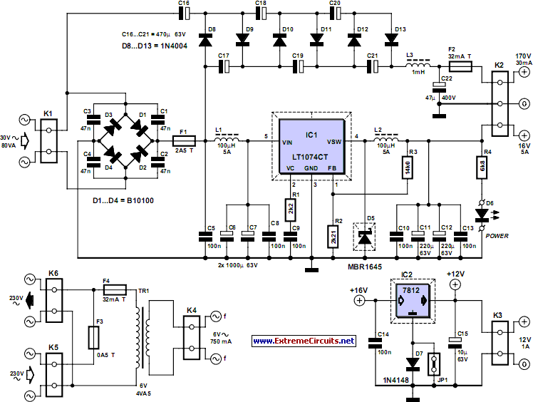
This power supply was designed for use with the Simple hybrid amplifier published elsewhere in this issue. It is suitable for various applications. A cascade generator is employed for the 170 V output, a switch mode supply for the...