
device Cheapest way to build or buy a remote controlled sound maker

This description suggests the development of a cost-effective electronic device that can perform tasks typically associated with more expensive alternatives. The device's functionality may include automation features, allowing it to operate independently based on pre-set schedules rather than requiring remote control.
For example, consider a programmable timer circuit that can control various appliances or systems. The circuit could incorporate a microcontroller, such as an Arduino or a PIC, which would allow users to input specific time settings for activation. The microcontroller can drive a relay module to handle higher voltage appliances, making it suitable for a range of applications, from turning lights on and off to controlling small motors.
The schematic for such a device would include the following components:
1. **Microcontroller**: The central unit that executes programmed instructions. It should be selected based on the required input/output pins and processing power.
2. **Real-Time Clock (RTC)**: This component keeps track of the current time, allowing the microcontroller to trigger actions at the specified times. Modules like the DS3231 can provide high accuracy.
3. **Relay Module**: Used to switch high voltage loads. The relay can be controlled by the microcontroller, allowing it to turn devices on or off based on the programmed schedule.
4. **Power Supply**: Ensures that the microcontroller and other components receive the necessary voltage and current. A regulated power supply would be essential for consistent operation.
5. **User Interface**: This could be a simple keypad and LCD display that allows users to set the time and configure other settings easily.
6. **Protection Components**: Diodes for flyback protection across the relay coils, fuses for overcurrent protection, and capacitors for voltage smoothing.
The overall design should prioritize safety, especially when dealing with high voltage circuits, and ensure that the user interface is intuitive for ease of programming. This approach not only reduces costs but also provides flexibility in functionality, catering to various user needs without the complexities associated with remote-controlled devices.A cheaper way to build or buy something with similar functionality It doesn`t necessarily even need to be remote controlled if it could be programmed to go off at certain times. 🔗 External reference
Related Circuits
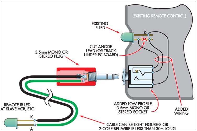
This ultra-simple remote control extender is ideal for use with a hidden video recorder. The recorder is a Panasonic NV-SD200 and is employed as part of a camera surveillance system. A PICAXE-08-based circuit detects events and controls the recorder....
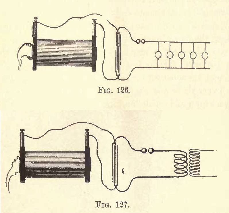
In relation to cold electricity, it aligns precisely with Duncan's statements. During experiments, burning wires were observed as a result of Tesla's work. Cold electricity refers to a phenomenon associated with electrical energy that exhibits distinct characteristics compared to conventional...
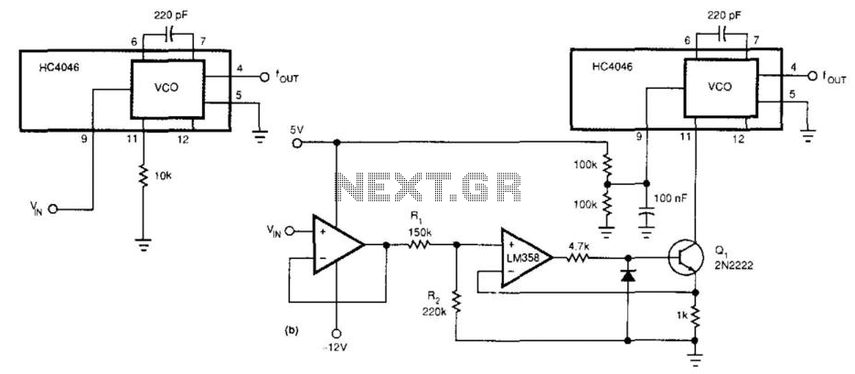
This circuit expands the linear frequency range of an HC4046 from one decade to nearly three decades. An LM358 is utilized as a constant-current sink, replacing the frequency-determining resistor (10 kΩ) connected from pin 9 to ground. For this...
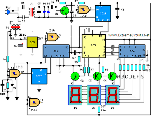
This circuit is designed for precise measurement of temperature in degrees Celsius. It features a transmitter section that converts the output voltage from a temperature sensor, which is proportional to the temperature being measured, into frequency. The resulting frequency...

This circuit is intended for precision centigrade temperature measurement, with a transmitter section converting to frequency the sensor's output voltage, which is proportional to the measured temperature. The output frequency bursts are conveyed into the mains supply cables. The...
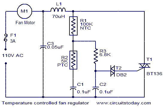
This fan regulator circuit automatically controls the speed of a fan based on temperature. It utilizes two thermistors (R1 and R2) for temperature sensing. The operation is similar to previously published designs, with thermistors replacing the potentiometer. As the...