
100Mhz Overtone Oscillator
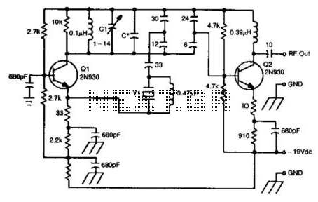
The oscillator circuit leveraging a 5th overtone crystal operates by utilizing the crystal's natural resonant frequency to generate stable oscillations. The 5th overtone refers to the fifth harmonic of the fundamental frequency, which provides improved frequency stability and selectivity compared to lower overtone crystals.
In this design, the crystal (Y1) is connected within a feedback loop that allows it to sustain oscillations at its resonant frequency. The circuit typically includes active components such as transistors or operational amplifiers, which amplify the oscillations generated by the crystal. Additional passive components like resistors and capacitors are used to shape the frequency response and stabilize the circuit.
The oscillator circuit's application in microwave frequency control is significant, as it ensures precise frequency generation necessary for various microwave devices, including RF transmitters and receivers. The stability provided by the 5th overtone crystal is critical in maintaining performance standards in communication systems and other electronic applications where frequency accuracy is paramount.
The design may also incorporate tuning elements to allow slight adjustments to the output frequency, accommodating for variations in component tolerances or environmental factors. Overall, this oscillator circuit exemplifies the integration of crystal technology in high-frequency applications, ensuring reliable operation within the specified frequency range. This oscillator circuit uses a 5th overtone crystal in the 85-to-106 MHz range. Y1 is the crystal. The circuit was originally used to frequency control a microwave oscillator. 🔗 External reference
Related Circuits
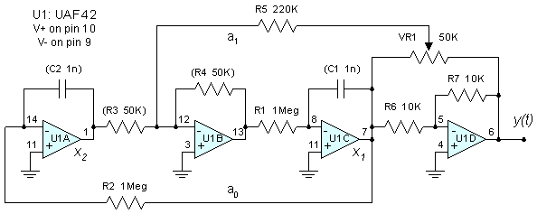
The major functional blocks necessary for designing a general-purpose audio oscillator are outlined, along with the details of the current prototype. The implementation is in the mode of an analog computer, as the desired outputs are sine and cosine...

This is a circuit known as a Wien bridge oscillator circuit. The circuit features both positive and negative feedback loops and operates under the control of an operational amplifier (op-amp). The oscillation frequency is determined by the RC time...
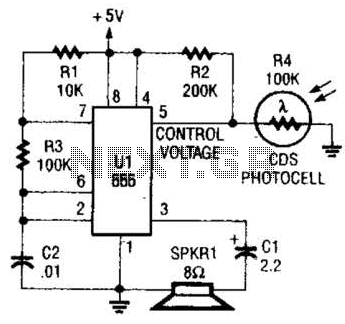
This circuit can be utilized as a light detector and potentially as a tool for individuals with visual impairments. The frequency of the oscillator is influenced by the level of illumination received by LDR4. The circuit operates by employing a...
This quartz crystal oscillator circuit exhibits greater stability compared to a parallel resonance circuit. It is capable of generating frequencies up to 30 MHz or even higher when utilizing BFR91 transistors for T1 and T2, along with reduced values...

This circuit is designed as a pocket-sized, high-performance audio oscillator. It can operate using a battery-powered version, which is feasible at a very low cost by utilizing a single quad op-amp to provide the entire active circuitry. The design...
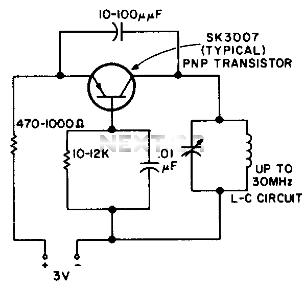
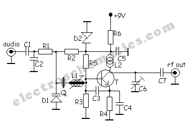
This RF oscillator is effective up to 30 MHz. An SK 3007 PNP transistor is recommended. The described RF oscillator circuit operates within a frequency range of up to 30 MHz, making it suitable for various applications in radio frequency...
Warning: include(partials/cookie-banner.php): Failed to open stream: Permission denied in /var/www/html/nextgr/view-circuit.php on line 713
Warning: include(): Failed opening 'partials/cookie-banner.php' for inclusion (include_path='.:/usr/share/php') in /var/www/html/nextgr/view-circuit.php on line 713