
two transistor led flasher

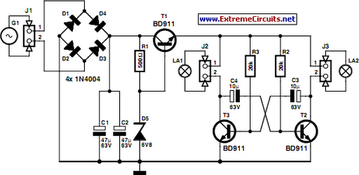
This circuit is designed to operate as a flashing LED indicator, serving as an attention-grabbing device or simulating a car alarm. The core component of the circuit is a bright red LED rated at 5000 mcd, which is responsible for the visual alert. The circuit's flashing behavior is controlled by a combination of resistors and capacitors, specifically R2 and C1, which define the timing characteristics. The flash duration is approximately calculated as three time constants, expressed mathematically as 3*R2*C1. This relationship allows for customization of the flash rate by adjusting the values of R2 and C1.
The brightness of the LED is managed by resistor R3, which limits the current flowing through the LED to approximately 20 mA. This is a critical specification, as it ensures the LED operates within safe parameters while maintaining sufficient visibility. The biasing of the transistors is achieved through R1, which must be set to a low enough value to prevent Q2 from saturating when the capacitor is disconnected, thus ensuring proper oscillation of the circuit.
In the event that the circuit fails to oscillate, adjustments may be necessary. If R1 is set too low or R2 is set too high, the circuit may not function as intended. Diode D1 plays a significant role by allowing for a higher duty cycle operation and protecting the base of transistor Q1 from reverse voltage, which is limited to -0.7 V. In applications where lower voltage operation (3-9 V) and reduced duty cycle are acceptable, D1 can be omitted, simplifying the circuit design.
The components required for this circuit are readily available from electronic suppliers, such as Radio Shack, making it accessible for hobbyists and engineers alike. Overall, this flashing LED circuit provides a straightforward and effective solution for creating a visual alert system.This circuit will flash a bright red LED (5000 mcd) as an attention getting device or fake car alarm. Component values are not critical and other transistors may be used. Flash duration is determined by R2 and C1 and is approximately 3 time constants (3*R2*C1). Brightness is controlled by R3 wich limits the LED current to about 20 mA for values li sted. R1 provides bias for the transistors which should be low enough not to saturate Q2 with the capacitor disconnected. If the circuit does not oscillate, R1 may be too low or R2 may be too high. D1 allows for higher duty cycle operation and limits the reverse voltage at the base of Q1 to -0. 7 V. D1 may be omitted for low voltage (3-9) and low duty cycle operation. Most parts available at Radio Shack. 🔗 External reference
Related Circuits
The LM3915 is a monolithic integrated circuit that senses analog voltage levels and drives ten LEDs providing a logarithmic 3 dB/step analog display. LED current drive is regulated and programmable, eliminating the need for current limiting resistors. The IC...

A balanced mixer circuit is illustrated using two dual-gate field effect transistors (FETs). The RF signal is coupled to the gates of these transistors through an input signal transformer (T1). Additionally, a local oscillation signal is introduced to the...

An infrared-sensitive phototransistor is employed to detect the temperature of a soldering iron. The phototransistor must be positioned to view the tip through an opaque tube to prevent interference from stray light, and it is advisable to equip the...
An exhaust fan is a crucial component in kitchens. This document presents a simple circuit designed to control kitchen fans by monitoring the ambient temperature. It is built around... The circuit for controlling an exhaust fan based on ambient temperature...
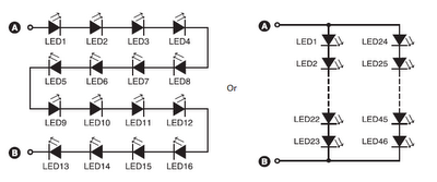
A series combination of 16 LEDs provides a luminance (lux) equivalent to a 12W bulb. However, if two series combinations of 23 LEDs are connected in parallel (totaling 46 LEDs), the output is equivalent to a 35W light bulb....
On a mountain bike, a common issue with traditional flashing LED lights from stores is the frequent problem of flat batteries and lights detaching. As an electronics student, a better solution was sought. A front wheel with a built-in...