
build relay toggle switch

The circuit described involves two relays, RL1 and RL2, which play a crucial role in controlling the switching mechanism for an application. Each relay consists of a coil and an armature, with RL1 primarily responsible for latching RL2. The relays are designed to operate at a resistance of 200 ohms, ensuring proper functionality within the circuit. The positive reference point is essential for turning off the relays, allowing for a clear state change when voltage is applied or removed.
The activation of switch S1 initiates a series of events that toggle the state of the relays. When S1 is pressed, RL2 is energized, which in turn latches RL1 on, allowing current to flow and maintain the state of RL2. The terminals are set to [A] during this operation, indicating that the application is active. Upon releasing S1, RL2 is deactivated, and RL1 remains latched, thus maintaining the desired circuit state until S1 is pressed again.
The use of resistor R1 is critical in this design, as it influences the current flow through the relays. The value of R1 must be adjusted based on the specific type of relays used in the circuit. For example, OEG relays with a 12V DC supply and a coil resistance of 270 ohms require R1 to be in the range of 60 to 70 ohms to ensure optimal performance.
This circuit design provides a practical solution for audio control without the need for mechanical toggle switches, enhancing user experience and flexibility. Furthermore, the ability to control the system remotely through a transmitted pulse adds an additional layer of convenience, allowing for operation from a distance. The overall design emphasizes reliability and ease of use, making it suitable for various applications in audio control systems.Half of RL1 and RL2 manipulate the switching and the other is connected to an application. Relays are 200 ohms above ground and at one point are referenced to positive that turns them off. RL1 (which is off) applies plus voltage from its armature and latches RL2 on . The application terminals are set to [A]. The condition changes when S1 is activated, voltage is applied to RL2 latching RL1 on releasing S1 turns RL2 off . RL2`s armature is then directed to R1. Terminals are set to [B]. When S1 is pressed again, the relays negative side are referenced to positive, RL1 turns off (there`s no current flow). RL2 turns on when S1 is released, terminals are set to [A]. There is slight lag between relays depending on how long S1 is held. If different relays are used, adjustment of R1`s value may be required. For example, OEG relays (12vdc, 270 ohm coil) need R1 at 60 - 70 ohms. The prime motivation for this design was to avoid using toggle switches for my audio control panel. Another plus, it can be controlled from a remote transmitted pulse. 🔗 External reference
Related Circuits
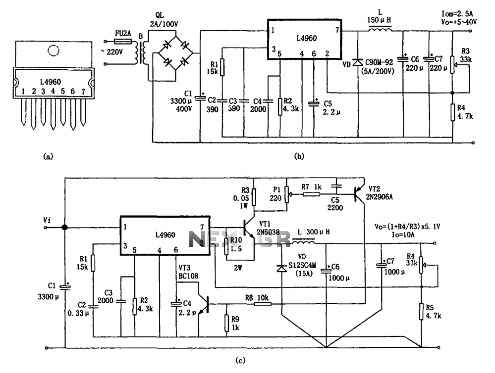
The circuit shown in the figure consists of an L4960 switching power supply that operates with an input voltage range of +5 to +40V. The AC 220V voltage is transformed down through a step-down transformer, followed by a bridge...
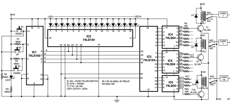
This circuit is capable of controlling one out of 16 devices using two push-to-on switches. An up/down counter functions as the master controller for the system, and visual feedback is provided through LEDs. The circuit employs IC1 (74LS193), which...
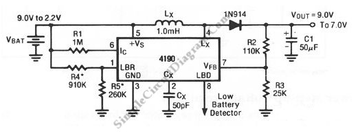
A standard 9V battery is considered depleted when its voltage drops below 7 volts. This switching regulator can extend the lifetime of a 9V battery. The circuit utilizes a switching regulator to optimize the energy usage of a standard 9V battery,...
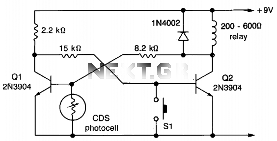
This circuit employs a flip-flop configuration utilizing Q1 and Q2. Under normal conditions, Q1 is heavily conducting. When light is detected by the CDS photocell, the bias on Q1 decreases, resulting in its cutoff, which activates Q2 and removes...

The circuit utilizes six 12-volt lead-acid batteries to power the load. Three batteries are connected in series to generate 36 volts, while the other three are connected in parallel to maintain 12 volts. The total discharge current is 30...
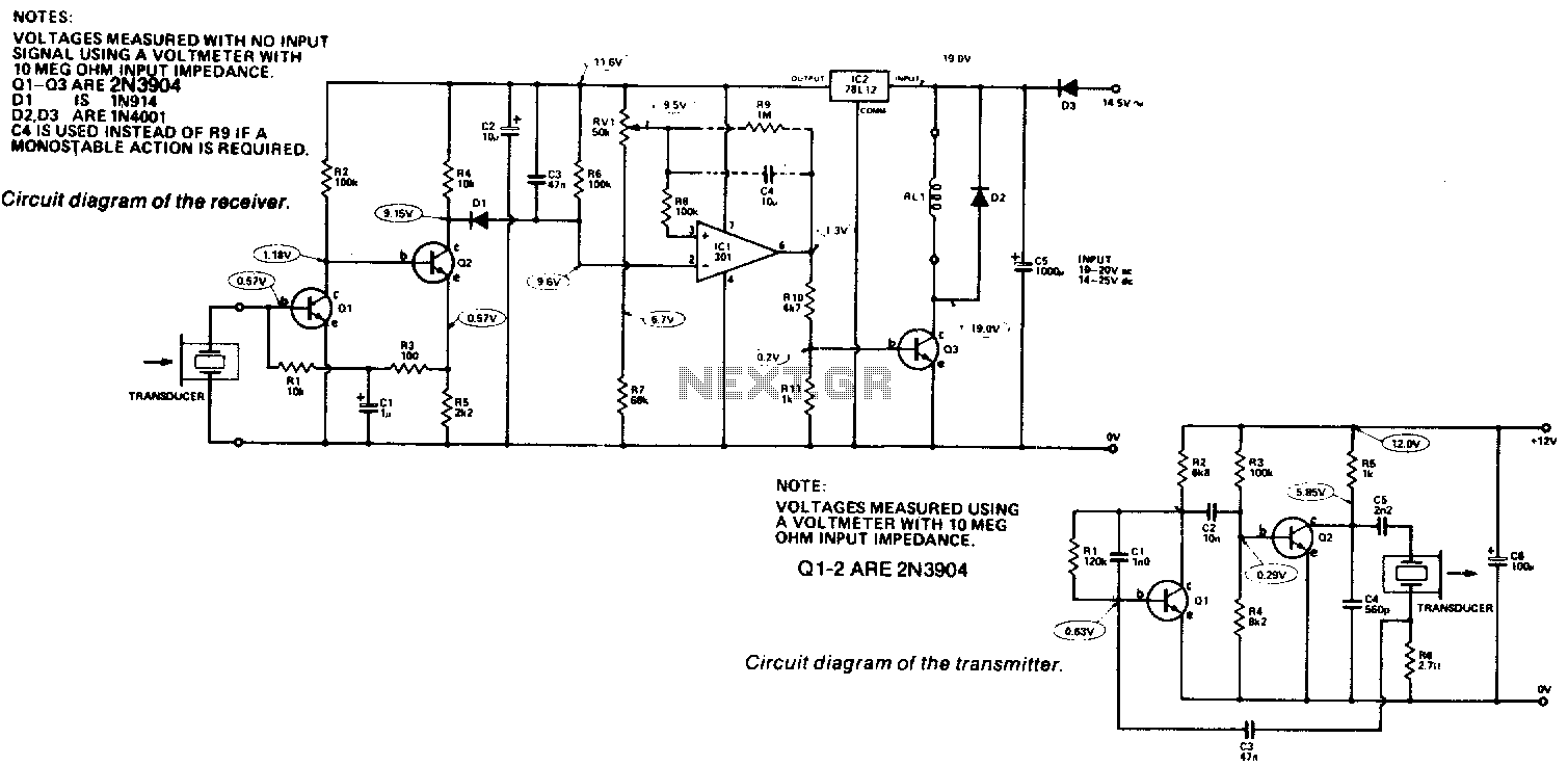
Receiver. The output from the transducer is amplified by Q1 and Q2, and rectified by D1. The voltage on pin 2 of IC1 will become more negative as the input signal increases. IC1 is utilized as a comparator, comparing...