
digital switching system
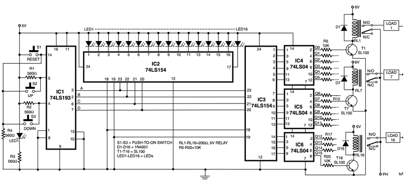
The circuit design incorporates a systematic approach to control multiple devices efficiently using a minimal number of components. The up/down counter (IC1) serves as the core of the system, facilitating both increment and decrement operations through user interaction with the push-to-on switches. The use of a presettable counter allows for flexibility in starting the count from any desired value, enhancing usability.
IC2, as a 1-of-16 decoder, translates the BCD output from the counter into a binary format that identifies which specific channel is currently selected. This is crucial for systems where multiple devices must be controlled independently. IC3 complements this function by ensuring that the selected channel is activated; it outputs control signals that correspond to the channel indicated by IC2.
The inverter gates (IC4 through IC6) play a vital role in ensuring that the triacs receive the correct polarity of signals for operation. This conversion from negative-going to positive-going pulses is necessary because triacs require a specific triggering method to operate effectively. The inclusion of NPN transistors allows for the amplification of control signals, providing sufficient current to drive the triacs, which are responsible for switching the connected devices on and off.
Furthermore, the diodes connected in series with the triac gates serve a protective function, ensuring that the gate receives a unidirectional current, thereby preventing potential damage to the triac from reverse polarity. This design consideration enhances the reliability and longevity of the circuit, making it suitable for various applications where multiple device control is necessary. Overall, this circuit exemplifies an efficient design for controlling multiple outputs with minimal user input while providing clear visual feedback.This circuit can control any one out of 16 devices with the help of two push-to-on switches. An up/down counter acts as a master-controller for the system. A visual indication in the form of LEDs is also available. IC1 (74LS193) is a presettable up/ down counter. IC2 and IC3 (74LS154) (1of 16 decoder/demultiplexer) perform different functions, i. e . IC2 is used to indicate the channel number while IC3 switches on the selected channel. Before using the circuit, press switch S1 to reset the circuit. Now the circuit is ready to receive the input clock. By pressing pressing switch S2 once, the counter advances by one count. Thus, each pressing of switch S2 enables the counter to advance by one count. Likewise, by pressing switch S3 the counter counts downwards. The counter provides BCD output. This BCD output is used as address input for IC2 and IC3 to switch one (desired channel) out of sixteen channels by turning on the appropriate triac and the corresponding LED to indicate the selected channel. The outputs of IC3 are passed through inverter gates (IC4 through IC6) because IC3 provides negative going pulses while for driving the triacs we need positive-going pulses.
The high output of inverter gates turn on the npn transistors to drive the triacs. Diodes connected in series with triac gates serve to provide unidirectional current for the gate-drive. 🔗 External reference
Related Circuits
The output voltage of a thermocouple is converted into a frequency that is measured by a digital frequency meter. The output signal from the thermocouple is proportional to the temperature difference between the hot junction and a reference thermostat...
This project will explain how I build my new wattmeter. This watt meter will be able to measure power from 300nW to 30W @ (0-500MHz). This wattmeter is based up on a dummy load of 50 ohm which can...
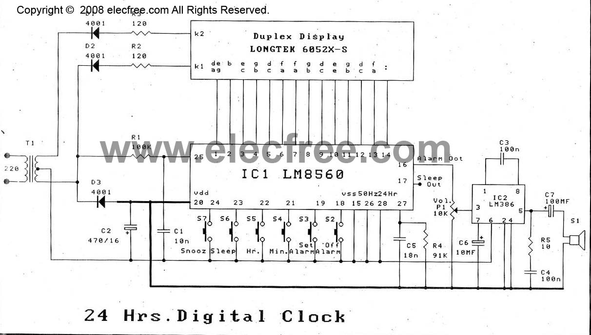
The digital time clock circuit is of great interest to electronic amateurs. The most popular clock ICs include the LM8361 and MM5387. Unfortunately, these ICs... The digital time clock circuit serves as an essential component for various electronic applications, providing...
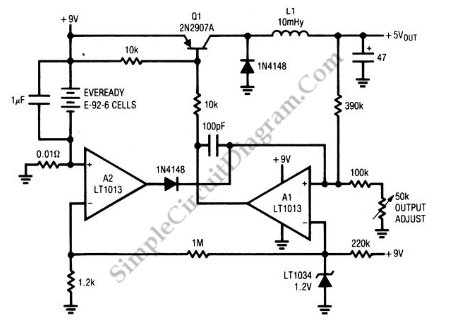
A circuit of a low-power switching regulator is illustrated in the schematic diagram below. This circuit can provide an output voltage of 5V from a 9V source. The efficiency... The low-power switching regulator circuit is designed to convert a higher...
A model RTX-70 exciter was originally utilized in the Brookdale ATV Repeater System. This document outlines the design considerations and new features of this exciter, including schematics of the circuits developed during its creation. The ATV exciter described employs...
The Car Voltage Gauge is based on 3 parts. The input circuit is an Analog to Digital Converter (IC2 CA3162E). The purpose of this chip is to sample an analog voltage and convert it to a decimal value which...