
build solar engine

The PIC16F84 microcontroller is a versatile device that can be employed in various applications, including robotics and control systems. Its architecture supports a range of features, including digital I/O, timers, and analog-to-digital conversion, making it suitable for complex control tasks. For programming the PIC16F84/A, a programmer circuit is necessary, which typically includes a serial interface for communication with a computer, as well as necessary voltage regulation and signal conditioning components.
The solar engine schematic operates effectively by utilizing a solar cell to harness energy from sunlight. This energy is stored in a 4700µF capacitor, which serves as a reservoir of electrical energy. The UJT plays a critical role in regulating the discharge of this energy. Upon reaching a certain voltage threshold, the UJT oscillates, generating a pulse that triggers the SCR. The SCR, once activated, allows the stored energy to flow to the HE-motor, enabling it to perform work, such as propelling a robot.
The integration of the solar engine with the PIC16F84 microcontroller can enhance the functionality of BEAM-type robots. The microcontroller can be programmed to manage the charging and discharging cycles of the capacitor, optimizing performance and energy efficiency. Additionally, sensors can be incorporated to allow the robot to respond to environmental stimuli, further increasing its autonomy and adaptability.
In summary, the combination of the PIC16F84 microcontroller and the solar engine design presents a powerful solution for creating energy-efficient robotic systems. The schematic provides a clear framework for understanding the operation of the solar engine, while the microcontroller offers extensive programming capabilities to enhance robotic functionality.Discussion about application of microcontroler PIC16F84 both for Control or Robotics and How to make Programmer of Microcontroller PIC16F84/A. The solar engine is commonly used as an onboard power plant for BEAM-type robots. Sometime called living robots. The inspiration for this solar engine originated from Mr. Mark W. Tilden who originally designed a solar engine. Another innovator was Dave Hrynkiw from Canada. He modified the solar engine design to power a solar ball robot. Below figure is schematic for the solar engine. This design are take from book with title Robot, Android, and Animatron by Jhon Iovine. Here is how it works. The solar cell charges the main 4700uF Capacitor as a power banks. As the capacitor charges the voltage level of the circuit increase. The UJT ( Uni Junction Transistor ) begin oscillating and sending a trigger pulse to the SCR ( Silicon Controlled Rectifier ). When the circuit voltage has risen to about 3 Volt from the main capacitor, the trigger pulse is sufficient to turn on the SCR.
When SCR turn on, all the stored power in the main capacitor is dumped trough the high efficiency motor ( HE-motor ). 🔗 External reference
Related Circuits
Wibowa Chou from IR discusses the benefits of fourth-generation IGBTs compared to MOSFETs, particularly in the context of a practical solar inverter application. Fourth-generation Insulated Gate Bipolar Transistors (IGBTs) offer significant advantages over Metal-Oxide-Semiconductor Field-Effect Transistors (MOSFETs) in various applications,...
The following circuit illustrates photovoltaic light sensors in a solar tracker. Features include accuracy, low cost, simplicity, and a single-axis electronic design. The photovoltaic light sensor circuit is designed to optimize the alignment of solar panels with respect to the...
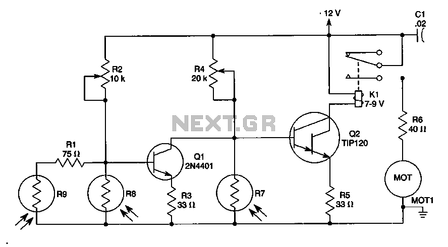
The sun trucker employs three photoresistors, R7, R8, and R9, to enable the circuit to track the sun during daylight hours while ceasing operation at night. Additionally, the circuit can be duplicated to achieve movement along four axes by...
A stereo valve phono preamplifier has been constructed by a technician. The device requires a power transformer and various components, excluding the valves, which the technician recommends sourcing based on individual needs. Experienced DIY enthusiasts are invited to share...
This is a simple NiCd battery charger powered by solar cells. A solar cell panel or an array of solar cells can charge a battery at more than 80% efficiency. The described circuit functions as a basic NiCd battery charger...
A newcomer has entered the field after completing several repairs and minor upgrades on tube amplifiers, including re-capping and addressing bias issues. The process of repairing and upgrading tube amplifiers involves several critical steps to ensure optimal performance and reliability....