
2 Axis Solar Tracker Circuit
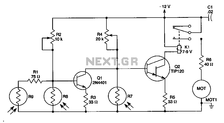
The sun trucker circuit is designed to harness solar energy effectively by utilizing a photoresistor-based tracking mechanism. The three photoresistors, R7, R8, and R9, are strategically placed to detect the intensity of sunlight from different angles. This arrangement allows the circuit to determine the direction of the sun's position in the sky.
When the sun's light hits the photoresistors, the resistance changes, generating a variable voltage output that can be read by a microcontroller or comparator circuit. The microcontroller processes the readings from the photoresistors and determines which direction the motors should move to align the solar panel with the sun. This alignment optimizes the panel's exposure to sunlight, thereby maximizing energy collection.
To enhance the system's capabilities, the circuit can be duplicated, allowing for movement along four axes. This is achieved by incorporating two motors, each responsible for controlling the movement in a specific axis. The first motor can control the azimuthal movement (left and right), while the second motor can handle the elevation (up and down) of the solar panel.
The circuit should also include a light-dependent resistor (LDR) or a similar mechanism to detect low light levels, which will trigger the motors to stop their operation at night. This feature is essential to prevent unnecessary wear on the motors and to ensure energy efficiency.
In summary, the sun trucker circuit is a sophisticated system that utilizes photoresistors for solar tracking and can be expanded for multi-axis movement through the addition of motors, making it an effective solution for maximizing solar energy capture.The sun trucker uses a combination of three photoresistors R7, R8 and R9, to ensure that the circuit will follow the sun during the day, but stop working at night time. Make this circuit 2 times to have 4 Axis move, by using 2 motors. 🔗 External reference
Related Circuits
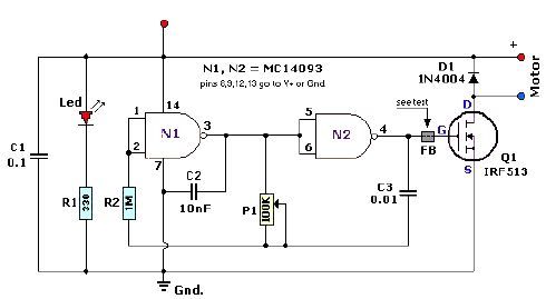
A quad 2-input NAND Schmitt trigger circuit can be designed using the MC14093 CMOS type IC, which serves as a simple pulse width modulation (PWM) controller electronic project. This PWM controller is straightforward and requires only a few external...

The following circuit illustrates the Ford Probe Single Wire Door Alarm System. This Single Door Locking Wire manages both LOCK and UNLOCK functions, indicating that the pulse wires must be connected to the same vehicle wire. The system primarily...

This is a simple 1.5V powered LED flasher circuit diagram. This circuit can flash 1.7V or 2.3V LEDs (depending on the color) using a 1.5V DC input. The LED will turn on when the 100µF capacitor is charged by...
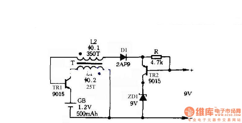
The circuit does not require a separate power switch or transformation to control the switches on the table. It offers advantages such as low power consumption, stability, reliability, and no impact on instrument accuracy. The transformer T in the...
This circuit is designed for the selection of alternative sources. It integrates mechanical selection through a rotating switch S1, electronic control of relays RL1 to RL10, and optical indication of the selection via the display DSP1. The circuit operates by...

There are digital and analog methods that can be used to compensate for the nonlinearity of a PT100 RTD. Digital linearization can be implemented through various techniques. Compensation for the nonlinearity of a PT100 RTD (Resistance Temperature Detector) is essential...