
Build Your Own Motorcycle Alarm

The circuit operates as a sophisticated security system for motorcycles, combining manual and automatic activation features. The intermittent siren output serves as an alarm mechanism, deterring potential theft or unauthorized use. The use of multiple normally-open switches enhances the system's responsiveness to various conditions, allowing for a tailored approach to security. For instance, the integration of tilt switches ensures that any movement of the motorcycle triggers the alarm, providing an additional layer of protection.
The adjustable timing components (R6, C4, R9, and C5) allow customization of the alarm's response, enabling users to set the desired duration for which the siren will sound after activation. This flexibility is particularly beneficial in adapting the system to different environments and user preferences.
The reliance on an electronic siren, rather than the motorcycle's horn, is a strategic choice to ensure the alarm system remains discreet and difficult to disable. The inclusion of a relay for higher current applications further enhances the reliability and safety of the circuit.
Protection against environmental factors is a critical consideration in the design. Ensuring that the circuit board and switches are shielded from moisture is essential for maintaining functionality in various weather conditions. The strategic placement of the 1-amp fuse close to the power source is a vital design aspect, safeguarding the wiring from potential overloads or shorts.
The design's quiescent current is nearly negligible, ensuring that the motorcycle's battery remains charged and operational, even when the alarm system is engaged. This feature is particularly advantageous for motorcycles that may not be used frequently, as it prevents battery drain.
Overall, this circuit represents a comprehensive approach to motorcycle security, combining advanced features with user-friendly operation and reliable performance. The inclusion of monitoring LEDs adds an innovative touch, providing visual confirmation of the alarm system's status and enhancing user confidence in its operation. The detailed support materials further ensure that users can successfully implement and test the system, maximizing its effectiveness in protecting their motorcycle.This circuit features an intermittent siren output and automatic reset. It can be operated manually using a key-switch or a hidden switch; but it can also be wired to set itself automatically when you turn-off the ignition. By adding external relays you can immobilize the bike - flash the lights etc. Any number of normally-open switches may be use d. Fit "tilt" switches that close when the steering is moved or when the bike is lifted off its side-stand or pushed forward off its centre-stand. Use micro-switches to protect removable panels and the lids of panniers etc Once activated - the rate at which the siren switches on and off is controlled by R9 & C5.
For example - increasing the value of C5 will slow it down - while reducing the value of R9 will make it faster. While at least one switch remains closed the siren will sound. About thirty seconds after all of the switches have been opened, the alarm will reset. How long it takes to switch off depends on the characteristics of the actual components used. You can adjust the time to suit your requirements by changing the value of R6 and/or C4. The circuit is designed to use an electronic Siren drawing 300 to 400mA. It`s not usually a good idea to use the bike`s own Horn because it can be easily located and disconnected.
However, if you choose to use the Horn, remember that the alarm relay is too small to carry the necessary current. Connect the coil of a suitably rated relay to the "Siren" output. This can then be used to sound the Horn - flash the lights etc. The circuit board and switches must be protected from the elements. Dampness or condensation will cause malfunction. Connect the 1-amp in-line fuse AS CLOSE AS POSSIBLE to your power source. This is VERY IMPORTANT. The fuse is there to protect the wiring - not the alarm. Exactly how the system is fitted will depend on the make of your particular machine - so I`m unable to provide any further help or advice in this regard.
The quiescent (standby) current of the circuit is virtually zero - so there is no drain on the battery. If you want to operate the alarm manually use a key-switch or a hidden switch connected to the "off/set" terminals.
For automatic operation connect a wire from the ignition circuit to the "ignit" terminal. Then every time you turn-off the ignition - the alarm will set itself. Remember that this wire from the ignition switch is not protected by your 1-amp inline fuse. So unless its run is very short - fit the wire with its own 1-amp fuse as close as possible to its source. When you set the alarm - if one of the switches is closed - the siren will sound. This could cause annoyance late at night. A small modification will allow you to Monitor The State Of The Switches using LEDs. When the LEDs are all off - the switches are all open - and it`s safe to turn the alarm on. The components are all drawn lying flat on the board - but those connected between close or adjacent tracks are mounted standing upright.
The links are bare copper wire on the component side. The Support Material for this circuit includes a detailed circuit description, A Circuit Simulation, a parts list, a step-by-step guide to construction - and details of how to Test Your Finished Alarm. 🔗 External reference
Related Circuits

The watchdog timer includes a counter, IC3, alongside the standard retriggerable 555 timer, IC1. The counter will sound an audible alarm if the watchdog timer attempts to reset a specified number of times (8, in the case of the...

This compact water sensor alarm circuit emits a loud warning sound when a humidity sensor detects the presence of water. The circuit utilizes the low-power comparator LM1801 from National Semiconductor. A fixed reference voltage for the integrated circuit is...
Transistors are configured as a Darlington pair in this circuit. A thermistor is utilized to detect or sense heat. A 12K variable resistor is employed to adjust the activation of the buzzer at the desired temperature. The operation of...

A CMOS-based motorcycle alarm circuit that features an intermittent siren output and automatic reset. It can be operated manually using a key switch or a hidden switch, and it can also be wired to set itself automatically. The CMOS-based motorcycle...
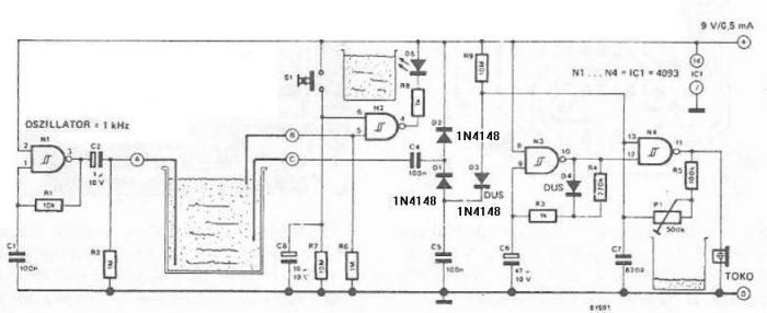
The circuit diagram is straightforward and operates as follows: the N1 Schmitt trigger functions as an oscillator, producing a frequency of approximately 1 kHz. When there is sufficient water in the tank, alternating voltage flows from electrode A to...

The circuit presented is a simple yet effective alarm system designed to protect an object. It requires no specialized devices and can be constructed using commonly available components. The primary alarm-triggering element is a reed switch. Any optical or...