
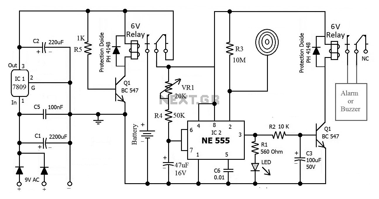
Simple Alarm System
The alarm-triggering element is a simple reed switch. To generate the alarm signal itself any optical or acoust ic device that operates on 12 V can be used: for example a revolving light, a siren, or even both. In the quiescent state the reed switch is closed. As soon as the reed switch opens, the input to IC1. B will go low (previously the potential divider formed by R2 and R3 held the input at 5. 17 V, a logic high level). A turn-on delay of between 0 and approximately 90 s can be set using P1, and a turn-off delay of between 0 and approximately 20 s can be set using P2. When the system is turned on (using S1), the turn-on delay is activated, giving the user of the system at most 90 s to leave the object alone before the system goes into the armed state, and the object is then protected.
Once the reed switch opens the turn-off delay of at most 20 s starts: this allows the rightful owner of the object to turn the system off before the alarm is triggered. If some unauthorised person causes the reed switch to open, the alarm will be triggered after the turn-off delay.
Also, even if the reed switch is briefly opened and then closed again, the alarm will still be triggered. Once the alarm is triggered, T3 will conduct for about 45 s (because of R8 and C5). The turning off of the alarm is necessary to avoid the nuisance caused by a permanently sounding alarm system.
The system then returns to the armed state, which means that the next time the reed switch is opened the alarm will trigger again. If it is not desired that the duration of the alarm be limited, for example if a visual indication is used, D5 should not be ¬tted.
The system can be extended by ¬tting multiple reed switches in series. As soon as any one is opened, the alarm is triggered. When S1 is closed C3 charges via P1. Depending on the potentiometer setting, it takes between 0 and 90 s to reach the input threshold voltage of IC1. A. The output of IC1. A then goes low and D3 stops conducting. Assuming the reed switch is closed, the inputs of IC1. B stay high and the output therefore low. If the reed switch is opened after the turn-on delay expires the output of the gate will change state and turn on T1.
This ensures that the output of the gate remains high even after the reed switch is closed again. C4 now starts charging via P2, reaching the input threshold voltage of IC1. C after between 0 and 20 s, again according to the potentiometer setting. The output of IC1. C goes low, and T2 and T3 are turned on and the siren sounds. Any Darlington transistor can be used for T3. At the same time, C5 charges via R8, reaching the input threshold of IC1. D in about 45 s. When the output of IC1. D swings low, it pulls the inputs of IC1. A low via diode D5: the siren stops and the system returns to the armed state. If the potentiometers P1 and P2 are replaced by ¬xed resistors it is possible to build the circuit small enough to ¬t in a match-box, without the need to resort to SMD components. This is ideal if the circuit is to be used to protect a motorbike. If the alarm system is to be used in a car, an existing door switch contact can be used instead of the reed switch.
In this case an RC combination needs to be added to prevent false triggering. Use a 10 µF/25 V electrolytic for C6, a 100 k © resistor for R9 and a 1N4001 for D7. It is again possible to wire multiple door switch contacts in parallel: as soon as one contact closes, IC1. B will be triggered. 🔗 External reference
Related Circuits
There is, and always has been, a marked lack of good, inexpensive lighting controllers for small theatre groups or musicians. The LX-800 Lighting System was designed with these applications in mind. More: As I said, this is an ambitious...
The hex switches are connected to J2 as follows: pin 1 is the common of both switches (+5V), pin 2 is the least significant bit (LSB) up to pin 5 which is the most significant bit (MSB) of the...
This is the circuit diagram of a touch-activated alarm system that remains operational during power outages. The alarm system is triggered when someone touches the designated touch plate. A notable feature of this circuit is the automatic battery activator,...

This alarm features both open-loop and closed-loop detection systems along with an automatic alarm shutoff mechanism. It provides a 15-second delay for exit and entrance. Additionally, the alarm activation time can be adjusted from 1 to 15 minutes. The alarm...

When the supply voltage drops below a minimum threshold, it is often advisable to disconnect the supply from the system to prevent poor performance or erratic operation. The circuit presented achieves this with minimal cost, board space, and complexity....
The simple audio mixer circuit is built on the common base principle, where input voltages are transformed into alternating currents which are summed to form the output. The simple audio mixer circuit utilizes a common base configuration to achieve effective...
Warning: include(partials/cookie-banner.php): Failed to open stream: Permission denied in /var/www/html/nextgr/view-circuit.php on line 713
Warning: include(): Failed opening 'partials/cookie-banner.php' for inclusion (include_path='.:/usr/share/php') in /var/www/html/nextgr/view-circuit.php on line 713