
building my own aux circuit car stereo feedback
Last weekend, a need arose for a portable player to connect to the car stereo. Upon inspection, it was discovered that the volume control is digital, making it impossible to tap an input at that location. The decision was made to insert a stereo 3mm canceling type jack (5 pin) at the volume control chip inputs, mounted on the front panel. A suitable jack was not found in the parts bins, so one was cannibalized from an old PC sound card. This solution is efficient, uncomplicated, and operates without relays, transformers, or sensing circuits. When the plug is disconnected, the radio plays its source normally. When the plug is connected, only the portable gadget provides audio, resulting in sound quality that surpasses that of the previously used FM modulator.
Advice was given regarding the use of a 3mm stereo jack on the front of the stereo and two RCA jacks on the back for an iPhone dock connector, where the RCA jacks require a sensing circuit. Ongoing refinement of the sensing circuit is planned for testing in the vehicle. A test harness is prepared for prototyping in the car. The stereo is an Alpine unit with an isolated, switching DC supply that could potentially be tapped if engine noise becomes an issue. Standard audio transformers from a ground loop isolator are utilized, ensuring frequency cutoffs are not problematic. Overall, direct wiring provides superior sound quality compared to the previously used cassette tape adapter.
The inputs on the volume chip were determined by tracing the PC board layout. The traces were cut to connect the jack. Further inquiries were made regarding the type of stereo used, which is a standard AM/FM model in a Geo Prizm. The receiver and audio sections are on separate boards, with the volume control connected to the audio board.
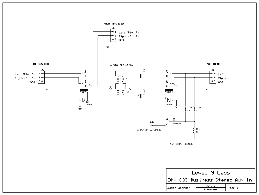
The circuit design incorporates a 3mm stereo canceling jack with five pins, which is crucial for switching between audio sources. The jack's configuration allows for seamless integration with the existing audio circuitry of the stereo system. The use of a 10k resistor ensures that the transistor remains in an "ON" state until an audio source is connected, at which point the relay disengages, allowing the audio signal to flow from the portable device.
The inclusion of 3.3uF capacitors serves to filter any unwanted noise that may arise from the input detection circuit, ensuring a clean transition between audio sources. The design is further enhanced by the use of isolation transformers, which help to mitigate ground loop issues, although it is noted that the grounds are connected in this particular setup.
For optimal performance, consideration may be given to the addition of shunting resistors or decoupling capacitors on the stereo side to further reduce any potential noise during the connect/disconnect process. This could enhance the overall audio quality and provide a more stable connection when switching between the portable device and the car stereo.By looking at the layout of the PC board, decided to insert a stereo 3mm canceling type jack (5 pin) at the volume control chip inputs, and mounted it on the front panel. Did not find such type of jack in my parts bins, and canibalized one out of a old PC sound card. Works well, simple, and does not need relays, transformers or sensing circuits. When the plug is removed, the radio plays its source normally. When inserting the plug, only the portable gadget feeds its audio source. It sounds much better than the FM modulator we tried before. With the detection part of the circuit, I`m simply holding the transistor "ON" with the 10k resistor, then looking for a path to ground through either L or R inputs via the 3. 3k resistor network. It seemed to work fine on the bench; the relay was held "ON" and when I connected an audio source, the relay switched off.
I added the 3. 3uF caps to keep the input detection part from "buzzing" the relay when it sensed the ground on the input side of the isolation transformers. Do you have any suggestions to improve my circuit Should I add some shunting resistors or decoupling caps to the stereo side to soften the connect/disconnect Isolation transformers are used to isolate grounds, but your grounds are connected together.
Even if you had separate grounds, the noise will pass through the transformers. With the detection part of the circuit, I`m simply holding the transistor "ON" with the 10k resistor, then looking for a path to ground through either L or R inputs via the 3. 3k resistor network. It seemed to work fine on the bench; the relay was held "ON" and when I connected an audio source, the relay switched off.
I added the 3. 3uF caps to keep the input detection part from "buzzing" the relay when it sensed the ground on the input side of the isolation transformers. Last weekend my daughter wanted to be able to play her portable player trough the car stereo, and after dismantling it, I found the volume control is digital and was unable to tap an input at the volume control.
By looking at the layout of the PC board, decided to insert a stereo 3mm canceling type jack (5 pin) at the volume control chip inputs, and mounted it on the front panel. Did not find such type of jack in my parts bins, and canibalized one out of a old PC sound card. Works well, simple, and does not need relays, transformers or sensing circuits. When the plug is removed, the radio plays its source normally. When inserting the plug, only the portable gadget feeds its audio source. It sounds much better than the FM modulator we tried before. Finally some useful advice! I actually have one of these jacks, and was considering using it, but I`m actually mounting a 3mm stereo jack on the front of the stereo _and_ 2 RCA jacks on the back to go to an iPhone dock connector, so the RCA jacks are the inputs that need a sense circuit.
I`ll continue to refine my sensing circuit and test it in the vehicle. I have a test harness all set up in the car and ready for prototyping! The stereo is an Alpine unit with an isolated, switching DC supply I could probably tap into if engine noise becomes an issue. I`m using standard audio transformers taken from a ground loop isolator, so the frequency cutoffs aren`t an issue.
Either way, direct wired sounds a whole lot better than the cassette tape adapter I was using!. How do you determine where the inputs on the volume chip are Did you cut the PC traces to them to patch in the jack Do you have any pictures you could post What kind of stereo was it It is a plain stock AM/FM in a Geo Prizm. Opened, saw the receiver section is in one board, the audio section in another board. The volume control attaches to the audio board. There i 🔗 External reference
Related Circuits
There are digital and analog methods that can be used to compensate for the nonlinearity of a PT100 RTD. Digital linearization can be implemented through various techniques. Compensation for the nonlinearity of a PT100 RTD (Resistance Temperature Detector) is essential...
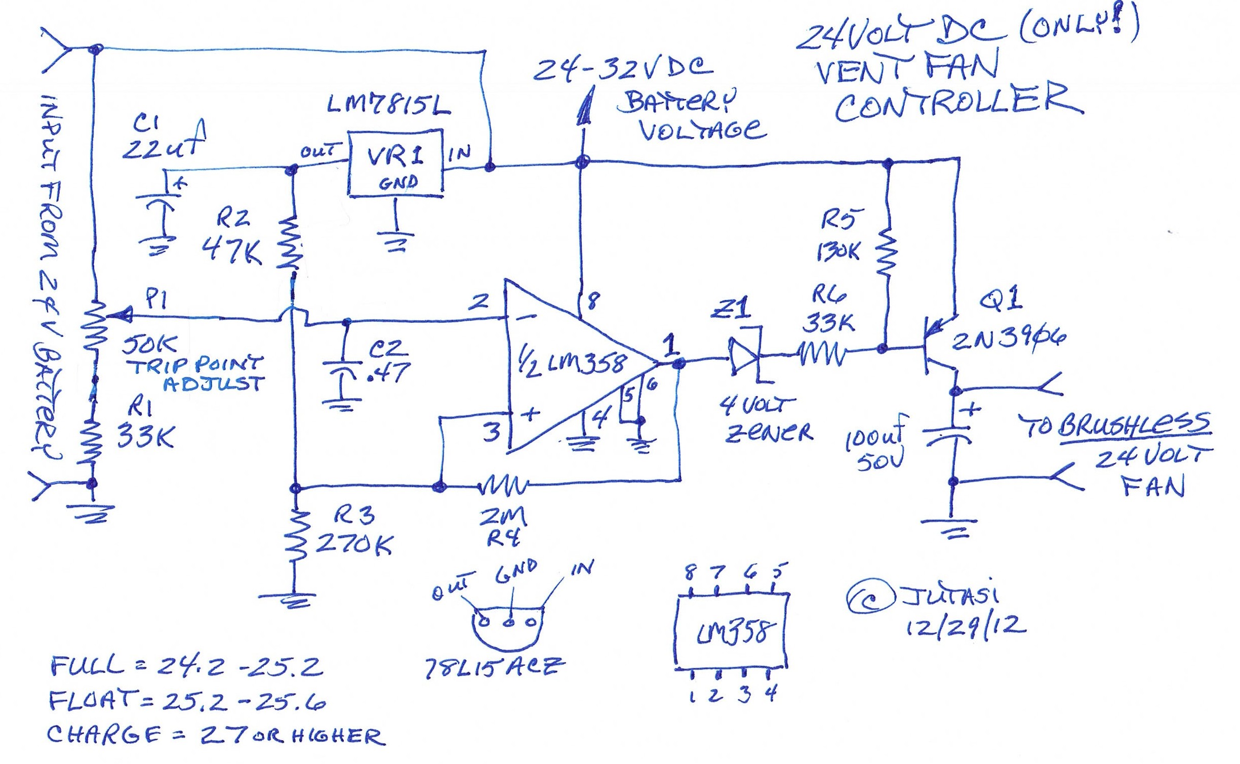
One of the backup systems utilizes a Magnum MS-PAE 4024 inverter, which lacks a built-in fan controller. Since batteries emit hydrogen during both normal and equalization charging, it is crucial to ventilate the batteries to the outside using a...
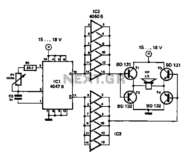
A low-cost and straightforward repellent circuit can be utilized for deterring rats, mice, and other animals, as illustrated in the electronic figure below. The circuit employs a CMOS integrated circuit of type 4047, which functions as a relaxation oscillator....
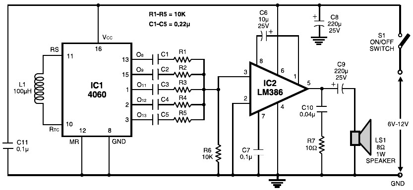
The circuit is built around the popular CMOS oscillator-divider IC 4060 and a small audio amplifier LM386. The IC 4060 functions as a multitone generator. A 100 H inductor is used at the input of the IC 4060, allowing...
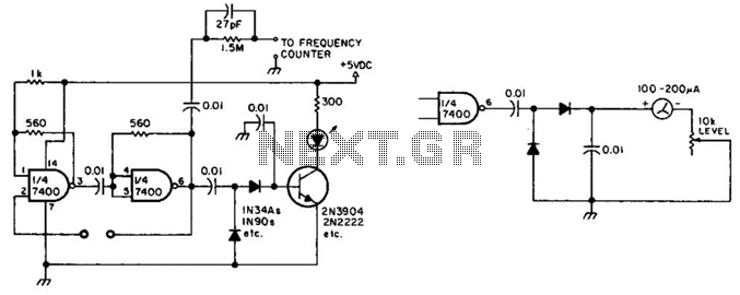
This circuit checks a crystal for activity. Two sections of a 7400 IC act as an oscillator, and its output is rectified to drive an NPN transistor that switches an LED. In an alternative configuration, a meter replaces the...
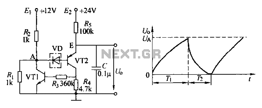
The application circuit depicted is a complementary sawtooth generator. In the schematic, VT1 is the transistor with a base current limiting resistor, which prevents excessive base current flow through the crystal tube. The resistor R4 acts as a bleeder...