
24 Volt Battery Box Vent Fan Control Circuit
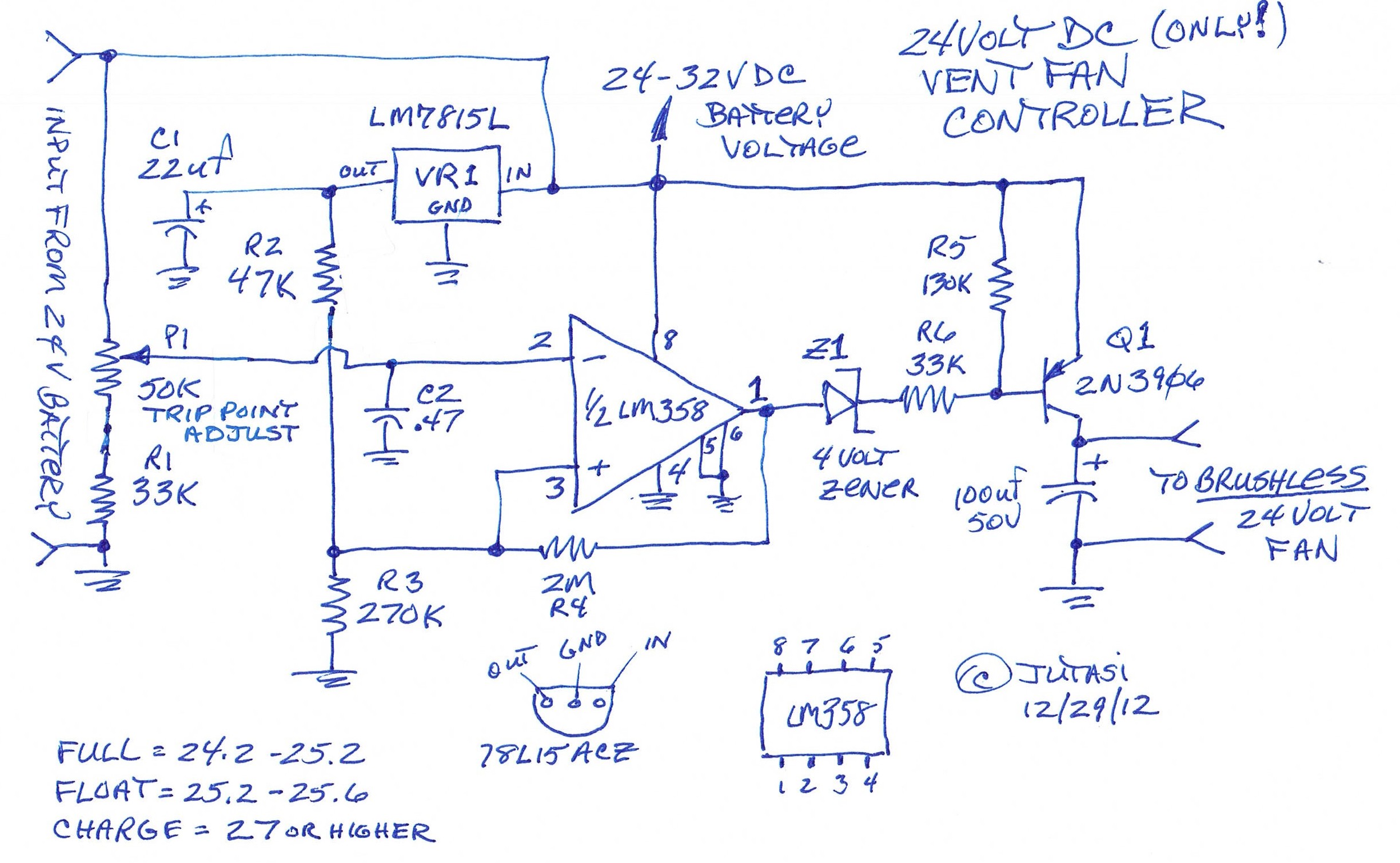
The circuit effectively manages the cooling of a 24-volt battery bank by using a simple but efficient control mechanism. The LM358 operational amplifier serves as the heart of the circuit, allowing for precise control over the fan operation based on the battery voltage. The variable resistor P1 allows for user adjustment of the trip point, enabling customization based on specific battery characteristics or environmental conditions.
The reference voltage stability provided by VR1, R2, and R3 is critical for ensuring consistent performance of the op-amp. This stability is particularly important in battery management systems where voltage variations can occur due to load changes or charging cycles. The hysteresis introduced by R4 is a key feature that prevents the fan from toggling rapidly, which can lead to wear and tear on the fan and reduce its lifespan.
The inclusion of a 4-volt Zener diode ensures that the Q1 transistor is fully turned off when not in operation, preventing any unintended current flow that could lead to overheating or inefficiency. The design allows Q1 to switch fans rated for up to 100 milliamps directly, making it suitable for smaller brushless fans. For applications requiring higher current fans, the circuit can easily be adapted by incorporating a relay that is activated by Q1, allowing for the control of larger loads without compromising the integrity of the original circuit.
Overall, this circuit design represents an effective solution for managing battery ventilation in a 24-volt system, promoting safety and longevity of the battery while ensuring efficient operation of the connected fan. Further developments could explore similar designs for 12-volt and 48-volt systems, expanding the applicability of this fan control circuit.One of my backup systems uses a Magnum MS-PAE 4024 inverter, which doesn`t have any built-in fan controller. Since batteries give off hydrogen during both normal and equalization charging, it`s important to vent the batteries to the outside with a brushless fan.
This little circuit does the job nicely for a 24 volt battery bank. Here`s how the cir cuit works: Battery voltage comes in and goes directly to the LM358 op-amp and P1-R1. P1 sets the trip point where the fan will turn on. VR1 and R2-R3 provide a stable reference voltage for the op-amp. R4 adds some hysteresis so the fan doesn`t cycle on/off when near the trip point. the 4 volt zener assures that Q1 turns fully off, since the output doesn`t swing to the rails. R5-R6 assure that Q1 turns on/off completely. Q1 is good for fans that use up to 100 milliamps of current. If you have a bigger fan, use Q1 to turn on a relay This won`t work for 12 volt or 48 volt systems, but I might design those if there`s any interest here . Enjoy! 🔗 External reference
Related Circuits
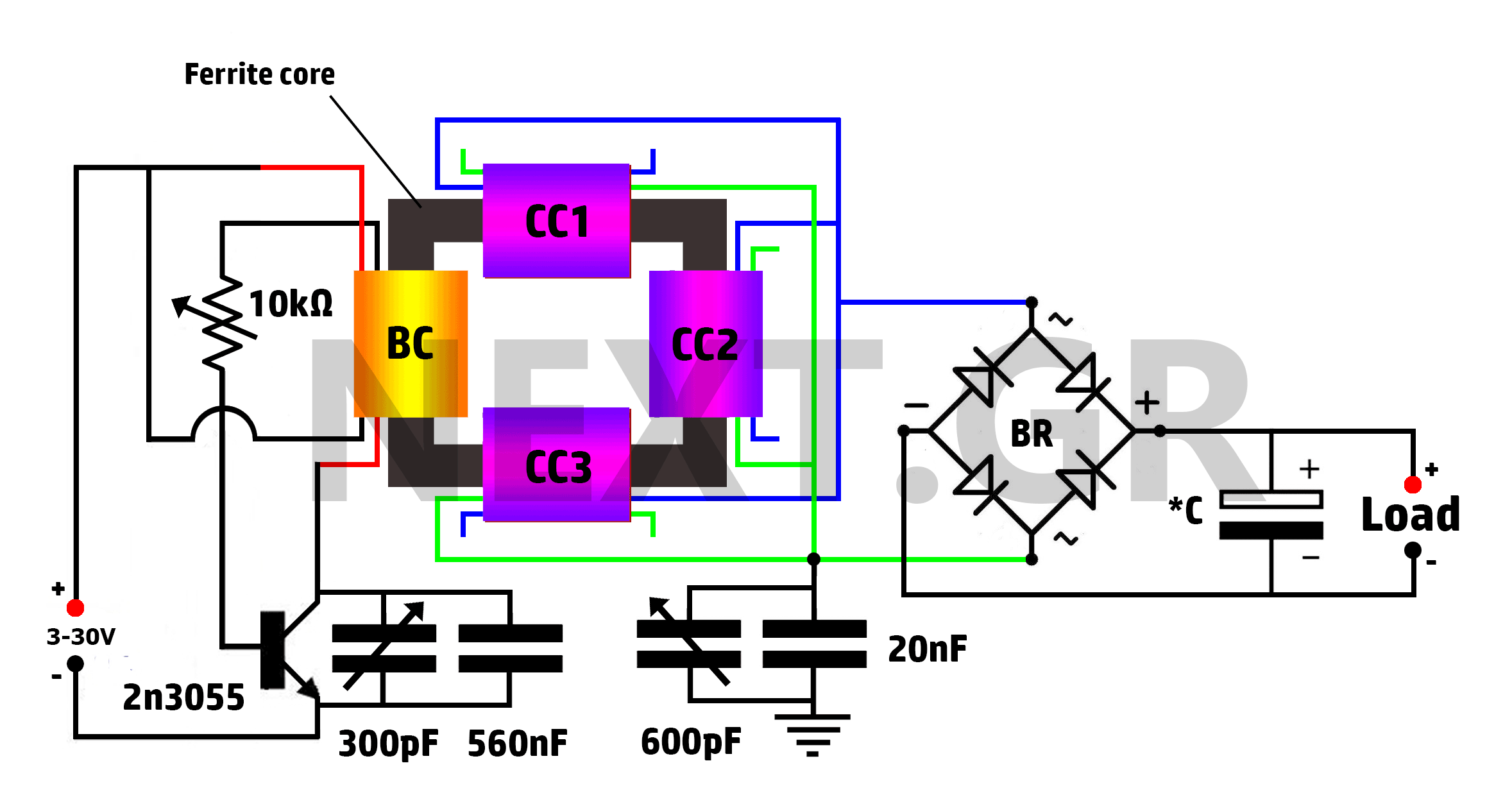
This is a Tesla/joule thief hybrid circuit that its inventor claims can produce 90 times the input power. The circuit can be self-looped and can provide 1050W of power, with only 11.6W looping back to supply the joule thief....
This circuit gradually switches the internal lights of a car on and off. The delay time can be adjusted by changing the values of the 10k and 4.7M resistors, as well as the capacitor. The circuit operates by utilizing a...
In an audio amplifier, the quality of sound depends on several factors, including the quality of active and passive components, circuit configuration, and layout. The selection of components is influenced by the constructor's budget. Discrete active components like transistors...
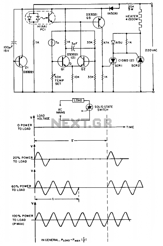
The "zero voltage switching" technique is commonly utilized to modulate heating and similar types of AC loads, where the time constant associated with the load (ranging from tens of seconds to minutes) is sufficiently long to allow smooth proportional...
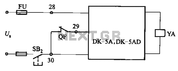
The DK-5A and DK-5AD AC power control circuit is illustrated in Figure 6-77. The figure includes a closing button (SBz) and a line (YA) connected to the closing electromagnet coil (U). This circuit is designed for the operation of...
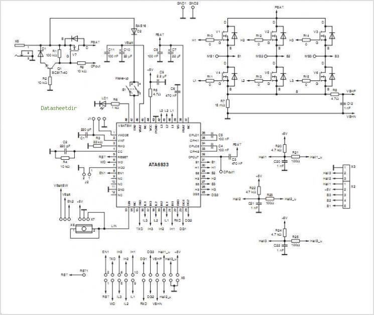
The T7024 is a single-supply front-end integrated circuit (IC) specifically designed for applications within the 2.4 GHz to 2.5 GHz frequency band. This front-end configuration includes a Power Amplifier (PA), a Low-Noise Amplifier (LNA), and a switch driver for...