
Bull horn
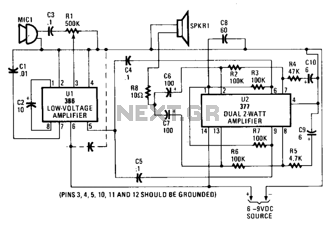
The circuit comprises a low-voltage audio amplification system utilizing an LM386 amplifier (U1) as the initial amplification stage. The input audio signal is processed through capacitor C3, which blocks any DC offset, ensuring that only the AC audio signal passes through to U1. Resistor R1, configured as a potentiometer, allows for adjustable gain control, enabling the user to modify the output volume to their preference.
U1 can be configured for various gain settings, providing flexibility depending on the application requirements. The output from U1 is delivered to a dual amplifier configuration (U2), specifically the 377 model, which is designed to amplify the signal further. This dual amplifier is connected in parallel, effectively doubling the output power to around four watts. The output coupling is achieved through capacitors C4 and C5, which serve to isolate the amplifiers from each other while allowing the audio signal to pass through.
Frequency stability in this circuit is crucial for maintaining sound quality. The stability is achieved through a combination of resistors R2, R4, and capacitor C10 on one side, paired with resistors R6, R5, and capacitor C9 on the opposite side. These components work together to form a feedback network that stabilizes the gain and frequency response of the amplifiers.
Finally, the outputs of both amplifiers are capacitively coupled to the speaker (SPKR1) via capacitors C6 and C7. This coupling ensures that any DC components are blocked, allowing only the amplified AC audio signal to drive the speaker. This design results in an efficient audio amplification system suitable for a variety of low-power audio applications.The input audio signal is fed to pin 3 of Ul, an LM386 low-voltage amplifier, via C3 and Rl. Potentiometer Rl sets the drive or volume level. Ul, which serves as a driver stage, can be set for a gain of from 20 to 200. The output of Ul at pin 5 is fed to U2—a 377 dual two-watt amplifier connected in parallel to produce about four watts of output power—at pins 6 and 9 via C4 and C5. Frequency stability is determined by R2, R4, and CIO on one side, and the corresponding components R6, R5, and C9 on the other side.
The outputs of the two amplifiers (at pins 2 and 13) are capacitively coupled to SPKR1 through C6 and C7. 🔗 External reference
Related Circuits

This circuit is a module for a diesel and horn train system. It is constructed using a 555 timer IC and several operational amplifiers (op-amps). The circuit serves as a complete system for the horn function. The main power...
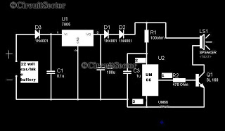
A simple musical horn circuit designed for use in cars or motorcycles can be connected to the 12V battery of any vehicle. This circuit is commonly utilized as a reverse musical horn. It employs the low-cost musical integrated circuit...
Gates U1-a and U1-b of the 4093 quad 2-input NAND Schmitt trigger are connected in variable, low-frequency square-wave oscillator circuits. The output of gate U1-a is connected to one of the inputs of gate U1-b. The square-wave output of...
Disconnecting the alarm system from the horn relay will eliminate the horn's sound during an actual alarm. This circuit silences the arming beep while maintaining the alarm by introducing a small delay into the signal. It is positioned between...
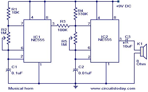
This document outlines a straightforward circuit diagram for a musical horn utilizing two NE555 integrated circuits (ICs). Both ICs are configured as astable multivibrators. The output from the first multivibrator is connected to the discharge pin (pin 7) of...
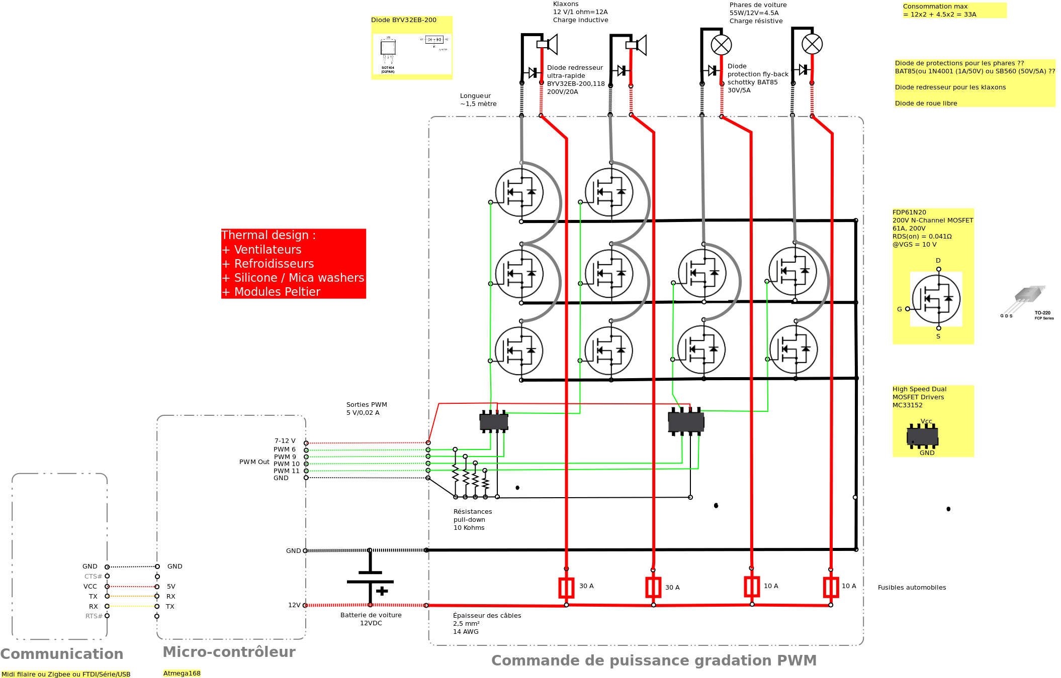
Past experiences were quite challenging due to the inductive nature of car horns, which require 12A of current, with peak demands reaching 20 to 30A. The current electronic system lacks reliability, given the high intensity. There is a need...