
Diesel and Horn Circuit for Train

This diesel and horn train circuit is designed to integrate seamlessly with the power and control systems of the train. The circuit utilizes a 555 timer IC, which, despite its limitations compared to more specialized components like the LM566, can still function as a basic VCO. The 555 timer operates by generating a pulse width modulation (PWM) signal that can be used to control the horn's activation based on the speed of the train.
The circuit's power supply requirements are critical for stable operation. A regulated 12 volts DC is essential to ensure that all components function within their specified ranges. The 13.5 VAC input to the rectifier bridge allows for the conversion of AC power into DC, which is then regulated to the necessary voltage. The rectifier bridge consists of diodes that allow current to flow in one direction, effectively converting the AC input into a usable DC output.
The connection points on the rectifier bridge (positions 3, 4, 5, and 6) are integral to establishing the circuit's functionality. Positions 3 and 4 are connected to the AC power supply, while positions 5 and 6 are utilized to derive the speed reference voltage. This voltage is crucial for determining the operational state of the train and ensuring that the horn is activated at the appropriate speeds.
The use of operational amplifiers in this circuit serves to enhance its performance. The op-amps are employed to condition the voltage signals, particularly to invert the positive voltage from the track. This inversion is necessary for the 555 timer to accurately interpret the speed of the train, as it requires a negative voltage range for proper operation. By inverting the voltage, the op-amps enable the 555 timer to produce a signal that correlates with the actual engine speed, allowing for precise control of the horn.
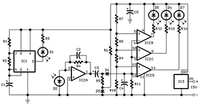
Overall, this circuit represents a well-thought-out integration of components that work together to provide a reliable and effective system for controlling the horn of a diesel train based on its speed. The careful consideration of power supply, voltage conditioning, and component selection contributes to the circuit's efficacy in a practical application.This is a one module of diesel and horn train circuit. This circuit is work with built by 555 timers IC, and some op amp. This circuit is a complete system for the horn circuit. This is the figure of the circuit. The main power supply to the system must be a regulated 12 volts DC with a minimum input from the train control AC or DC power supply of 13. 5 VAC connected to pos 3 and 4 of the rectifier bridge. The ground bus of the regulated 12 volts supply must be connected to the system ground. The independent speed reference voltage is taken directly from the train speed control module or can be taken by connecting directly from the tracks to positions 5 and 6 of the rectifier bridge. The output of this bridge will always be a positive speed voltage signal whichever direction the train is going.
The 555 timer is really a poor replacement for the LM566 as a VCO (Voltage controlled oscillator) although it is linear in function a negative voltage range is needed to activate the timer and produce the RPM to relate to the actual engine speed thus the op-amp is used to invert the track positive voltage. 🔗 External reference
Related Circuits
This circuit was designed to assist in parking a car near a garage wall while reversing. LED D7 lights up when the distance to the wall is approximately 20 cm. When the distance reduces to about 10 cm, both...
This circuit diagram represents a microphone preamplifier, specifically designed to prioritize voice signals over other audio inputs. In its basic configuration, the circuit includes a microphone unit and a change-over switch that connects to an amplifier. When the push-to-talk...
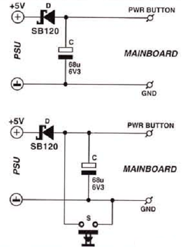
Many enthusiasts utilize their PCs as data loggers, controllers, or web servers. In such instances, it is crucial to ensure that the machine remains powered for as much time as possible, even during a power outage or if the...
The 22-watt amplifier is straightforward to construct and cost-effective. This circuit can serve as a booster in a car audio system, an amplifier for satellite speakers in a surround sound or home theater setup, or as an amplifier for...
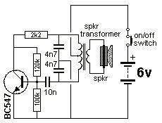
The Colpitts Oscillator is characterized by tapping the mid-point of the capacitive side of the oscillator section. The inductor can be the primary side of a speaker transformer. The feedback comes via the inductor. The Colpitts Oscillator is a type...
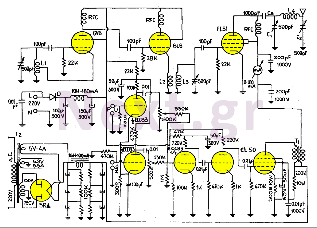
This transmitter, equipped with a quality antenna and utilized under optimal conditions, can achieve a range exceeding 45 km. The configuration benefits from the output lamp's elevation, enhancing the fidelity of the transmitted signal. The 6V6 lamp is employed...
Warning: include(partials/cookie-banner.php): Failed to open stream: Permission denied in /var/www/html/nextgr/view-circuit.php on line 713
Warning: include(): Failed opening 'partials/cookie-banner.php' for inclusion (include_path='.:/usr/share/php') in /var/www/html/nextgr/view-circuit.php on line 713