
HORN CIRCUIT_FOR_MOTORCYCLE_USE
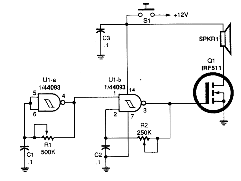
The described circuit employs two gates from the 4093 quad 2-input NAND Schmitt trigger to create a variable low-frequency square-wave oscillator. The configuration leverages the inherent hysteresis of the Schmitt trigger, which provides stable switching characteristics, allowing for the generation of clean square waves even at low frequencies.
In this setup, the output of gate U1-a is fed back to one of the inputs of gate U1-b. This feedback loop is crucial as it allows gate U1-a to trigger gate U1-b, resulting in a modulation effect that produces a two-tone output. The frequency of oscillation can be adjusted by varying the resistor and capacitor values connected to the gates. Typically, a capacitor is connected between the output of gate U1-a and the ground, while resistors are connected to the inputs of both gates to set the timing characteristics.
The unique aspect of this configuration is the interaction between the two gates, which can create complex waveforms when the circuit parameters are fine-tuned. By adjusting the resistor values or the capacitor size, the frequency and duty cycle of the output waveform can be altered, leading to a variety of interesting audio outputs. This circuit can be particularly useful in sound synthesis applications, where unique tonal qualities are desired. The resulting two-tone output can be further processed with additional circuitry for effects or amplification, enhancing its applicability in electronic music production or sound design.Gates U1-a and U1-b of the 4093 quad 2-tnput NAND Schmitt trigger are connected in variable, low-frequency, square-wave oscillator circuits. The output of gate U1-a is connected to one of the inputs of gate U1-b. The square-wave output of gate U1-a modulates oscillator U1-b, producing a two-tone output. A really interesting sound can be producecl by carefu.. 🔗 External reference
Related Circuits
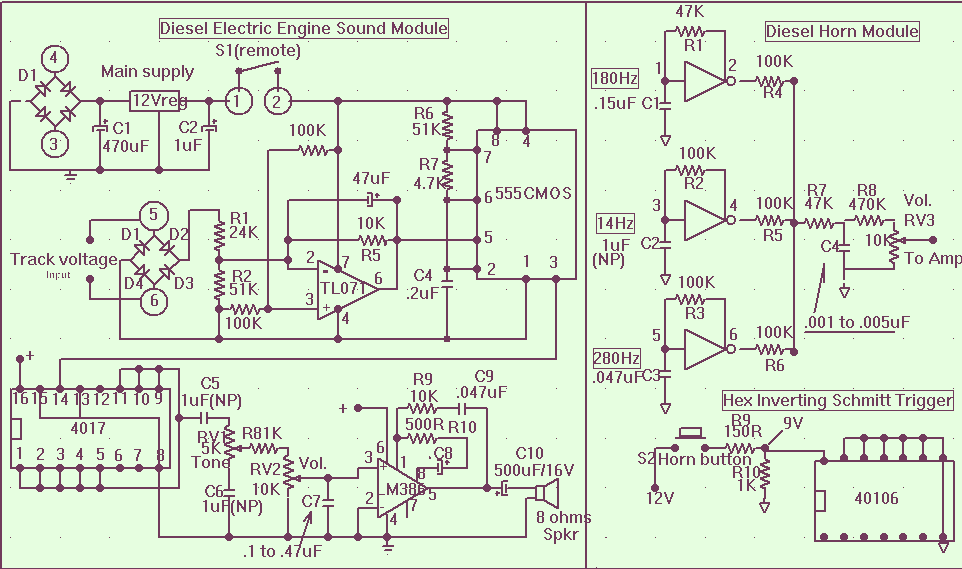
The main power supply to the system must be a regulated 12 volts DC with a minimum input from the train control AC or DC power supply of 13.5 VAC connected to pos 3 and 4 of the rectifier...
The following diagram is the schematic diagram for a car horn circuit that can be utilized for car modifications. Components List: R1 = 68K, R2 = 2K2, R3 = 56K, R4 = 3K3, R5, R6 = 4K7, R7 =...
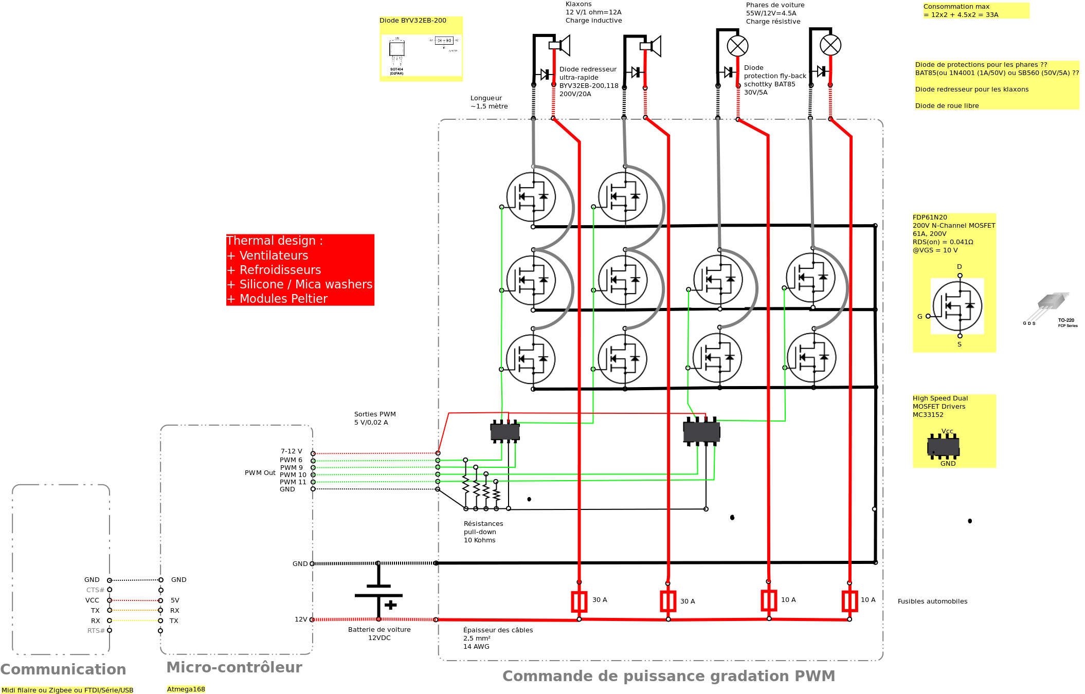
Past experiences were quite challenging due to the inductive nature of car horns, which require 12A of current, with peak demands reaching 20 to 30A. The current electronic system lacks reliability, given the high intensity. There is a need...
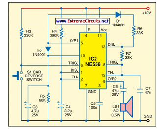
This circuit activates the car horn when the vehicle is in reverse gear. It utilizes a dual timer NE556 to generate the necessary signals. The described circuit employs a dual timer IC, specifically the NE556, which is a versatile component...
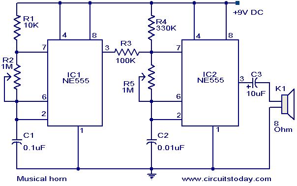
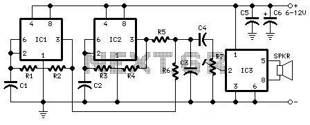
This document outlines a straightforward circuit diagram for a musical horn utilizing two NE555 integrated circuits (ICs). Both ICs are configured as astable multivibrators. The output from the first multivibrator is connected to the discharge pin (pin 7) of...
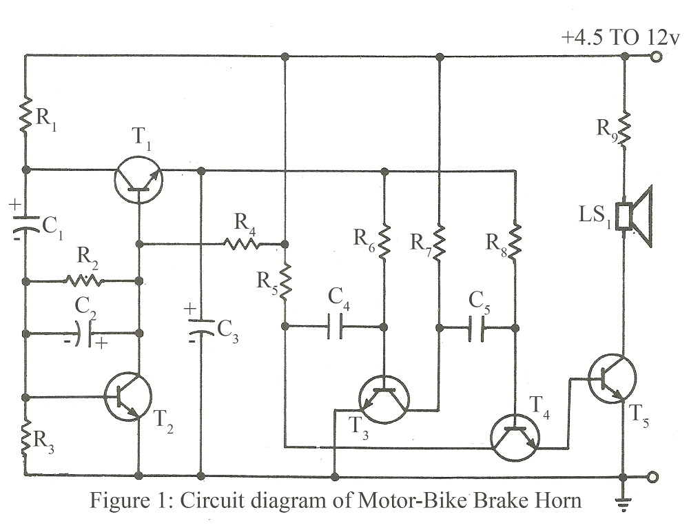
The circuit is designed to operate within a voltage range of 4.5V to 12V DC, or it can be directly connected to the brake point of a motorcycle. Resistor R7 should be replaced with a 1-ohm, 1/2W resistor when...