
Musical horn circuit
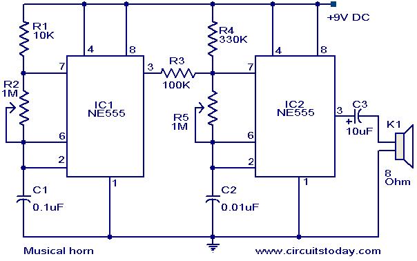
The circuit employs two NE555 timers, which are versatile and widely used in various applications due to their reliability and ease of use. In this setup, each NE555 operates in its astable mode, producing continuous square wave signals. The frequency of oscillation for each NE555 can be adjusted by selecting appropriate resistor and capacitor values connected to their timing pins.
The first NE555 timer generates a square wave signal that serves as a trigger for the second NE555 timer. This configuration allows for the modulation of the output frequency of the second NE555 based on the frequency of the first. By adjusting the resistors and capacitors in the circuit, different musical tones can be produced, which can be amplified and used to drive a speaker or buzzer, effectively creating a musical horn.
In practical implementation, the circuit requires careful consideration of component values to ensure that the desired frequency range and tonal quality are achieved. Additionally, the power supply voltage for the NE555 ICs should be selected to match the specifications provided in the datasheet, typically ranging from 4.5V to 15V, to ensure optimal performance. Proper decoupling capacitors should also be included near the power supply pins of the ICs to minimize noise and improve stability.
Overall, this simple circuit design demonstrates the use of NE555 timers in creating sound-producing devices, showcasing their versatility in electronic applications.Here is a simple circuit diagram of a simple musical horn using two NE555 ICs. Two ICs are wired as astable mutivibrators. The output of first multivibrator is given to the discharge (pin 7) of the second astable multivibrator. The combined effect of the astable multivibrators produces a musical tone at the output. 🔗 External reference
Related Circuits
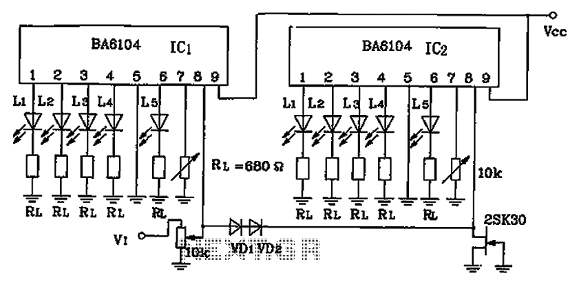
BA6104 is a five-digit LED level meter that functions as an LED display driver integrated circuit (IC). The configuration of the circuit is illustrated in the accompanying figure. The circuit utilizes a 10 by two-dot LED level display. The...
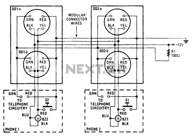
An intercom utilizing dual-modular wall jacks is depicted in this circuit. If the wires are accessible in the home telephone cable, this system can be installed with minimal difficulty. The intercom system described employs dual-modular wall jacks, which are standard...
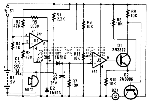
In the circuit, U1 amplifies the audio captured by the condenser microphone. Resistor R1 limits the current, while R2 and R3 center the amplifier's output to a voltage level of %B+ to facilitate the use of a single-ended power...
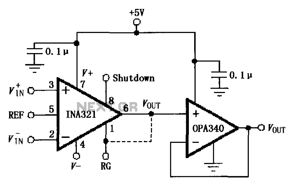
The circuit depicted in the figure consists of an OPA340 operational amplifier configured as a voltage follower, serving as an output buffer for the INA321/322 output. The optimal load impedance for the INA321/322 is 10k ohms or greater. A...
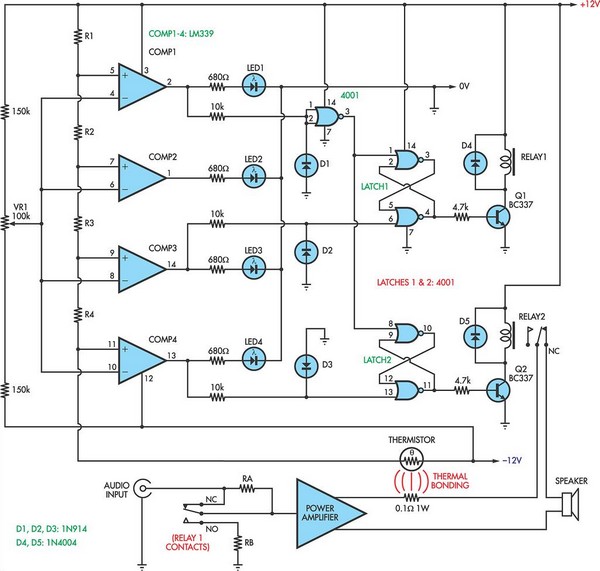
When the voltage on the non-inverting input of each comparator exceeds the voltage at its inverting input, the output transitions to a high state, activating the corresponding LED. NOR gate latches are connected to the outputs of the third...
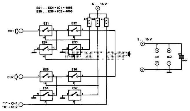
This combination sync stripper and universal video interface can solve various problems, including interfacing Super Nintendo with other devices, video overlay, and locking TV frames for scopes. Kits, fully tested units, and custom cable assemblies are available through Redmond...
Warning: include(partials/cookie-banner.php): Failed to open stream: Permission denied in /var/www/html/nextgr/view-circuit.php on line 713
Warning: include(): Failed opening 'partials/cookie-banner.php' for inclusion (include_path='.:/usr/share/php') in /var/www/html/nextgr/view-circuit.php on line 713