
Burglar Alarm with 555
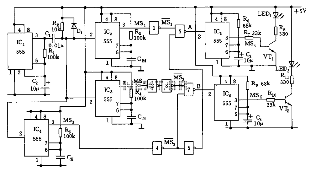
The alarm circuit utilizes two 555 timer integrated circuits (ICs) configured in monostable and astable modes to achieve its functionality. The first 555 timer is set up in monostable mode to create a delay when the alarm is armed. When the switch S1 is closed, the circuit becomes active. The timer is initiated by opening the normally closed switch S2, which allows the user approximately five seconds to exit the vehicle and close the door. The timing of this delay is determined by the resistor R1 and capacitor C1, which can be selected to provide the desired exit delay.
The second 555 timer is configured to monitor the status of the car door. If the door is opened while the circuit is armed, the timer starts counting. The time delay before the alarm triggers is set to two seconds, which is adjustable through the resistor R2 and capacitor C2. If the door remains open for longer than this duration, the circuit activates the car horn, creating an audible alert. The output of the second timer is connected to a relay or transistor that controls the power to the car horn, ensuring that the alarm is loud enough to be heard.
To deactivate the alarm, the user must close switch S2, which resets the first 555 timer and stops the horn from sounding. This circuit design is not only applicable to automotive security but can also be adapted for home security applications, providing a simple and effective solution for protecting personal property. Proper selection of components and careful layout of the circuit board will ensure reliability and performance in various environments.This alarm circuit is based on two 555 timers. The alarm will sound your car horn if anyone opens the car door while the circuit is armed. The timers will allow you to leave the car without sounding the horn. To turn the circuit on S1 must be closed. To set the alarm, open S2 ( it is normally closed ) this will give you about 5 seconds to get out and close the door. The exit delay time is set by R1 and C1. If anyone opens the doors for more then two seconds the horn will sound until power is removed from the circuit.
The 2 second time is set by R2 and C2. If you open the door, you must deactivate the alarm by closing S2. This very basic circuit could be used for a home also. 🔗 External reference
Related Circuits
The following article discusses a few very simple intrusion detector circuits, or burglar alarm circuits. The presented designs are straightforward yet highly effective in their functions. The triggering stage may consist of a voltage/current amplifier stage combined with a...
The capacitor filter operates by measuring the capacitance, which is proportional to the pulse width. This measurement is compared to a nominal capacitance to determine qualification. The circuit, as illustrated in the accompanying figure, includes IC1 along with resistors...
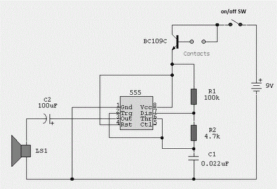
The circuit uses a 555 timer wired as an astable oscillator and powered by the emitter current of the BC109C. Under dry conditions, the transistor will have no bias current and be fully off. As the probes get wet,...
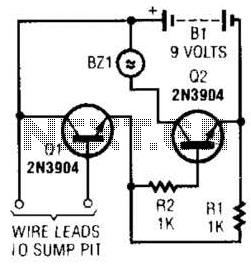
A common collector amplifier drives a 2N3904 switch to sound alarm BZ1. The wire leads to a water sensor or sump pit, level switch, etc. It is used to allow the alarm to operate and be mounted in a...
This stun gun is powered by a 9V battery. The transformer steps up the voltage to about 1800V (but with very low current). A 555 timer IC is used to generate a high-frequency output. A 1 MEG variable resistor...
Probes or contacts may utilize a non-reactive metal. Gold or silver plated contacts from an old relay may be used; however, a cost-effective alternative is to wire alternate copper strips from a piece of veroboard. These will eventually oxidize,...