
Stun Gun with 555
The circuit operates on a 9V battery, which serves as the primary power source. The 555 timer integrated circuit (IC) is configured in astable mode to produce a square wave signal at a high frequency, typically in the range of several kilohertz. This high-frequency output is essential for driving the transformer effectively, allowing it to step up the voltage.
The transformer utilized in this circuit is a high-voltage transformer designed to increase the voltage from the 9V input to approximately 1800V. It is crucial to note that while the voltage is significantly high, the output current remains low, which is a characteristic feature of stun gun circuits. This combination of high voltage and low current is what allows the device to deliver a painful shock without causing fatal harm.
In addition to the transformer, a 1 MEGΩ variable resistor can be integrated into the circuit at the output. This component serves as a means to adjust the output voltage, providing the user with the ability to control the intensity of the shock. However, the inclusion of this resistor is optional and may be omitted depending on the design preferences of the builder.
Safety precautions are paramount when constructing or handling this circuit. The high voltage output can induce a painful shock if contact is made with the output leads. Proper insulation and safety measures should be implemented to prevent accidental contact with the high-voltage components. It is recommended that individuals with adequate knowledge of high-voltage electronics should undertake the construction and testing of this stun gun circuit.This stun gun is powered by a 9V battery. The transformer steps up the voltage to about 1800V (but with very low current). A 555 timer IC is used to generate a high-frequency output. A 1 MEG variable resistor can also be used at the output to drop the voltage, but this is optional. If you build this circuit, be careful, as it outputs a high voltage. Touching the output leads will induce a painful shock. 🔗 External reference
Related Circuits
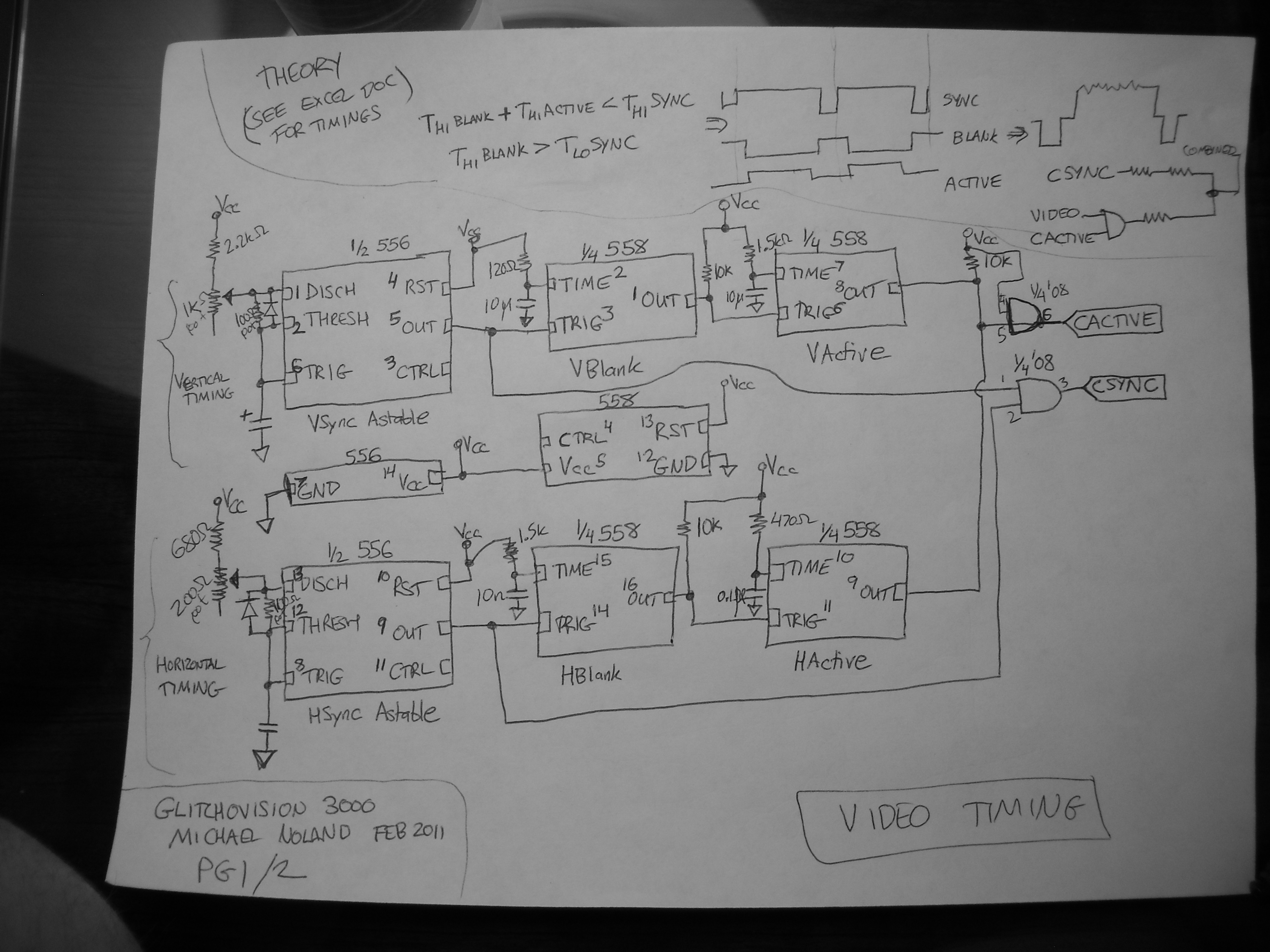
This entry describes a four-step sequencer that controls an Atari Punk synth, accompanied by a grayscale NTSC video visualization of the output audio. The system is constructed using two 558 quad-timers and two 556 dual-timers. The video quality may...
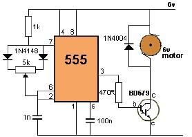
This project utilizes a 555 timer to control the speed of a 6-volt DC motor. Speed adjustment is achieved by rotating a 50 kΩ potentiometer either to the left or right. The circuit employs a 555 timer configured in astable...

The described circuit counts the number of interruptions of an infrared beam. This could be used to tally the number of people entering a room or to monitor how often an object, such as a ball, passes through an...
The proximity switch using the 555 timer functions as a monostable trigger circuit. The trigger pin (Pin 2) of the 555 timer is connected through a large resistor (R2) to the positive supply voltage (VDD) and is in a...

A simple electronic key code lock circuit that requires few external components can be constructed using this schematic diagram. This electronic key code lock circuit is based on a common 555 timer circuit and other standard components. This low-cost...

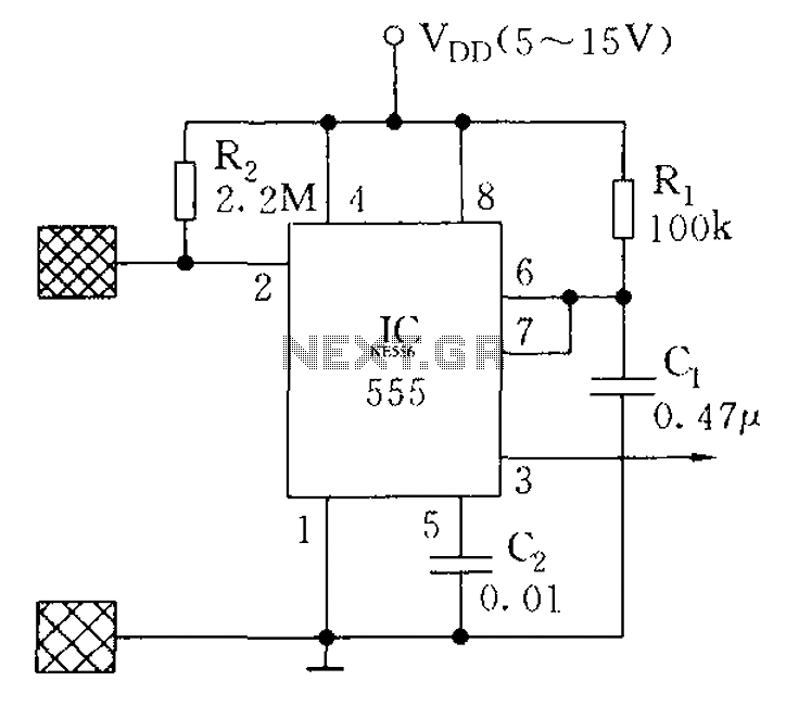
This circuit is constructed using the widely recognized LMC555 timer integrated circuit (IC). It is commonly employed in laboratory power supplies and various test and measurement equipment. The LMC555 timer IC is a versatile component that can be configured in...