
buzzer set

The competition buzzer set is designed for use in educational settings, particularly for contests and quizzes that require quick responses from participants. The core components of the kit include a printed circuit board (PCB) that serves as the foundation for the electronic assembly. The PCB is etched but remains undrilled, allowing users to customize the layout according to their specific requirements.
The programmable logic device (PLD) included in the kit is pre-programmed to manage the buzzer's functionality, ensuring that it responds accurately and efficiently during competitions. The 556 timer, a versatile dual timer IC, is utilized to control timing functions within the system, allowing for precise response intervals. This is critical in competitive scenarios where timing can influence the outcome.
The assembly process is designed to be straightforward, with a comprehensive manual guiding users through each step. This manual includes schematics and wiring diagrams that illustrate the connections between components, ensuring that even those with minimal experience can successfully complete the project. The additional parts required for assembly are readily available at local electronics supply stores, making it convenient for users to source what they need.
The final product, once assembled, is robust and capable of withstanding the rigors of classroom use. The design emphasizes durability, which is essential for environments where multiple users interact with the equipment. Moreover, the option to modify the buzzer set to include a large LED wall display significantly enhances its functionality, making it suitable for larger audiences. This modification is detailed in the assembly manual and includes a schematic that provides a clear pathway for integration.
Overall, the competition buzzer set represents an excellent educational tool, combining hands-on learning with practical application in a competitive format. The project not only fosters electronics skills but also promotes teamwork and engagement among students.Building a Competition Buzzer Set, described the construction of a contest buzzer set. Additional reference material and parts are available, as described below: A kit includes an etched, undrilled printed circuit board, a programmed PLD, a 556 timer, miscellaneous mounting hardware, and a more detailed assembly manual. The kit costs $35. You will need about $25 to $30 in additional parts, available from standard electronics supply stores. I estimate about ten hours total assembly time is required, using this kit. If you are good at fairly simple electronics projects (or can talk to an electronics teacher or student into helping you) this is a good way to save money.
The fully assembled and tested unit is just like the one pictured here. It comes with assembly and operations manuals. The unit looks good, is well constructed, and is durable (even when used by high school students). While it is not a commercial unit (we assemble and test it ourselves), it is a nice unit at an attractive price of $250. We do not keep these units in stock, so there is a delay in filling orders. This delay can be from a couple of weeks to a couple of months, depending on the availability of good student labor here to assemble them.
A detailed assemble manual is available for plans for a modification to the contest buzzer set to add a large LED wall display to make the display visible to a large group. A schematic is also available. This was developed by Richard Levergood at Londonerry High School. 🔗 External reference
Related Circuits
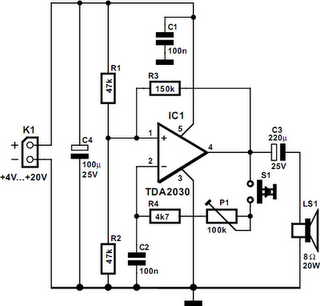
A powerful buzzer in the room, combined with a pushbutton at the bottom of the stairs or in the kitchen, could be very useful in such situations. The core of this circuit is formed by IC1, a TDA2030. This...
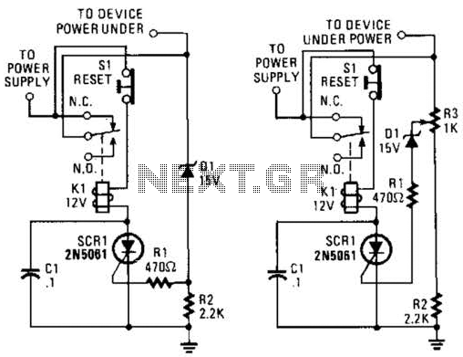
If circuits experience frequency overvoltage conditions, continually replacing blown fuses can become quite costly. This shutdown circuit addresses that issue by substituting the fuse with a relay and a low-current SCR. When the input voltage exceeds the threshold established...
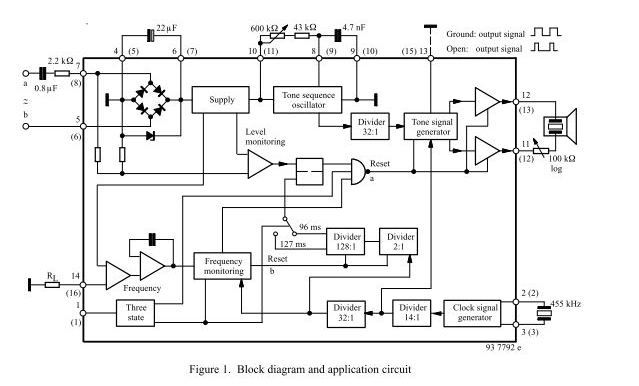
The three-tone ringing integrated circuit U4076B, in conjunction with a piezo transducer or loudspeaker, replaces the normal electromechanical telephone bell. It is operated with the ringing current frequency. The U4076B integrated circuit is designed to generate a three-tone ringing signal,...
This novel buzzer circuit uses a relay in series with a small audio transformer and speaker. When the switch is pressed, the relay will operate via the transformer primary and closed relay contact. As soon as the relay operates...
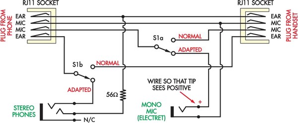
Here is a more affordable and simpler method to create a telephone headset adapter. The only components needed are an inexpensive headset (available for $5 at Harvey Norman), a DPDT switch, and... To construct a telephone headset adapter using the...
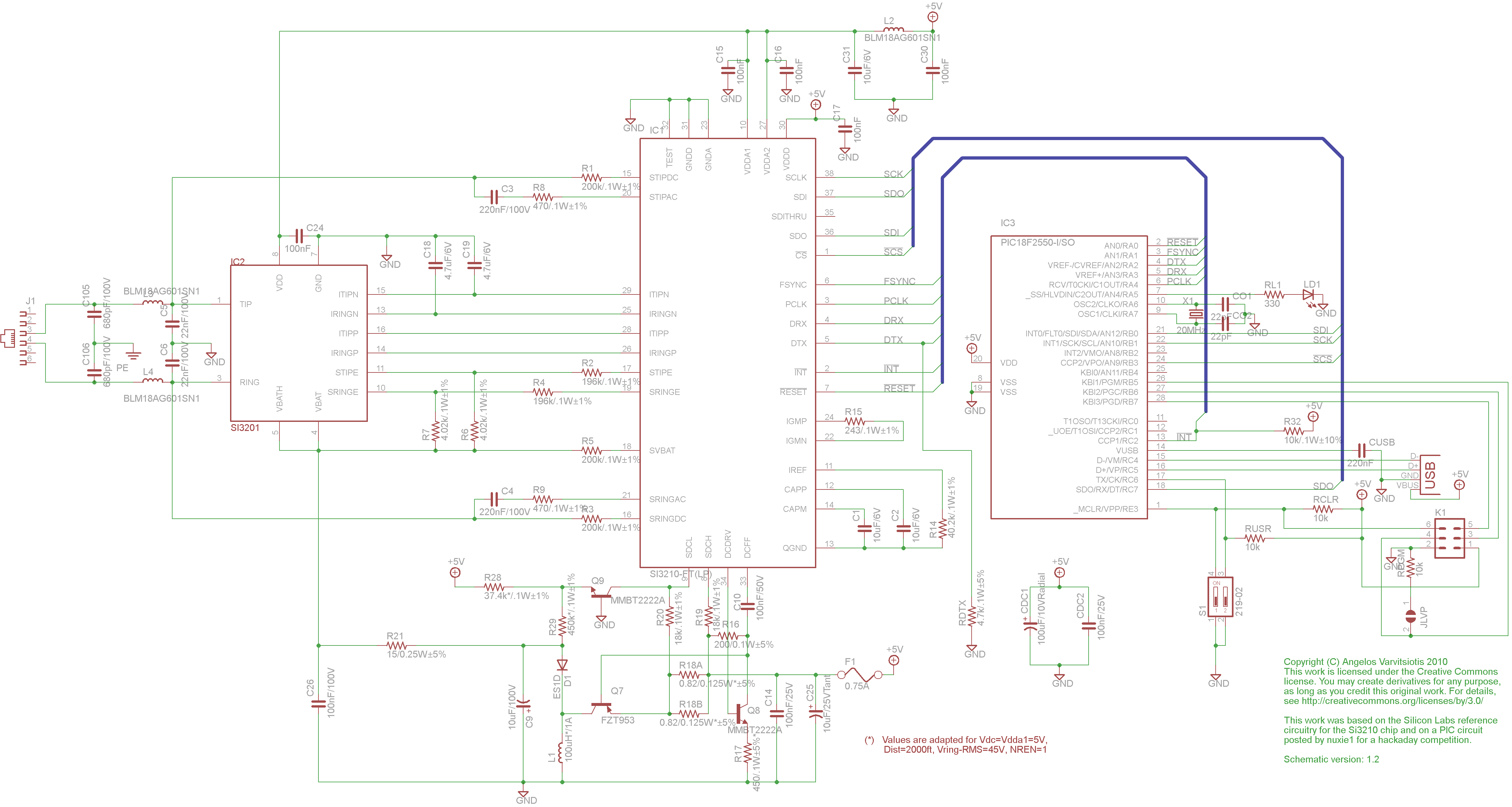
This page discusses the differences between assembled Open USB FXS dongle boards and DIY boards. While the assembled boards are fully tested and quality control approved, DIY boards may encounter various issues during assembly. Fortunately, most of these issues...