
Power Buzzer
The described circuit is designed to activate a buzzer when a pushbutton is pressed, providing an audible alert in specific situations, such as when someone is at the bottom of the stairs or in a kitchen area. The TDA2030 integrated circuit serves as the primary amplifier in this configuration, capable of driving the buzzer with sufficient power while ensuring stability and reliability due to its thermal protection features.
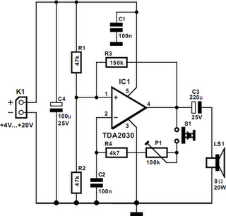
The resistors R1 and R2 are configured as a voltage divider, ensuring that the positive input of the op-amp receives a stable reference voltage, which is critical for proper operation and oscillation. Resistor R3 is essential for creating positive feedback, which is necessary for the oscillation process. The values of R1, R2, and R3 must be carefully selected to achieve the desired gain and feedback characteristics.
The frequency of the oscillation, which directly affects the sound produced by the buzzer, is determined by the values of capacitor C2, resistor R4, and the adjustable trimmer potentiometer P12. The trimmer allows for fine-tuning of the frequency, enabling customization of the buzzer's sound output according to user preference.
In summary, the circuit effectively combines a pushbutton switch and a buzzer, utilizing a TDA2030 integrated circuit to generate an audible alert. The design emphasizes reliability and customization, making it suitable for various applications where alert signals are necessary. Proper component selection and configuration are crucial for achieving optimal performance in this buzzer activation circuit.A powerful buzzer in the room, combined with a pushbutton at the bottom of the stairs or in the kitchen, could be very handy in such situations. The heart of this circuit is formed by IC1, a TDA2030. This IC has built-in thermal protection, so it`s not likely to quickly give up the ghost. R1 and R2 apply a voltage equal to half the supply voltage to the plus input of the opamp. R3 provides positive feedback. Finally, the combination of C2, R4 and trimmer P12 determines the oscillation frequency of the circuit. Power Buzzer Circuit Diagram. 🔗 External reference
Related Circuits
The circuit shown demonstrates how to power one or two LEDs from a 120-volt AC line by utilizing a capacitor to reduce the voltage and a small resistor to limit the inrush current. Because the capacitor needs to conduct...

An electronic rectification circuit that avoids the use of large, heavy, and expensive electrolytic capacitors by utilizing an active transistor in a gyrator configuration. To minimize excess ripple output on a power supply feeding a heavy load, a large...
The Universal Serial Bus (USB) has become a popular method for connecting computer peripherals. The original USB 1.1 specification limited data rates to approximately 12 Mbits/sec, while the updated USB 2.0 specification increases these rates to up to 480...
This chapter includes circuit diagrams for various power supplies designed for pulsed solid-state lasers. It features units that are compatible with the widely used Hughes ruby and YAG rangefinder laser assemblies, one utilizing the flash from a disposable pocket...

A current transformer H11-3 needs to be constructed. Select a transformer core with a minimum power rating of 2W for the first secondary winding. Use enameled wire with a diameter of 0.12 mm and wind approximately 1000 turns. The...
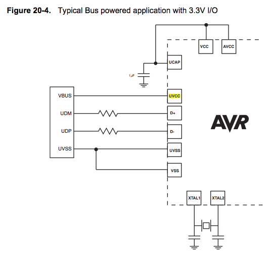
Since the microcontroller unit (MCU) is powered through USB, the common zero voltage should align with the supply voltage and thus be connected to the 0V (UVSS) line. In electronic circuit design, it is essential to ensure that the ground...