
Nicad Battery Charger circuit
The circuit operates by employing the BD140 transistor to regulate the charging current delivered to the load. The 1N4148 diodes serve as a reference voltage source, establishing a stable voltage level that is necessary for the proper biasing of the transistor. This configuration ensures that the charging current remains constant, regardless of variations in the load or supply voltage.
In this design, the base-emitter junction of the BD140 is activated by the voltage drop across the two 1N4148 diodes, which typically amounts to approximately 1.4V when forward-biased. This biasing allows the transistor to operate in its active region, maintaining a constant current output. The output current can be adjusted by changing the value of the resistor connected to the emitter of the BD140, thereby allowing for flexibility in the charging current based on the specific requirements of the application.
The overall circuit is efficient and straightforward, making it suitable for various low-power charging applications. It is important to ensure that the transistor's maximum ratings are not exceeded during operation, and appropriate heat sinking may be required depending on the load conditions. Additionally, the choice of diodes and their placement within the circuit can affect the overall performance and stability of the charger.his simple charger uses a single transistor as a constant current source. The voltage across the pair of 1N4148 diodes biases the base of the BD140 medium power transistor.. 🔗 External reference
Related Circuits
The double-ended working core square wave inverter transformer area product formula Bm represents the maximum magnetic flux. The primary side of the transformer features switches S1 and S2 in parallel with IRF32055. This parallel configuration is primarily due to...
This is a programmable clock timer circuit that utilizes individual LEDs to display hours and minutes. Twelve LEDs can be arranged in a circular pattern to represent the 12 hours on a clock face, while an additional 12 LEDs...
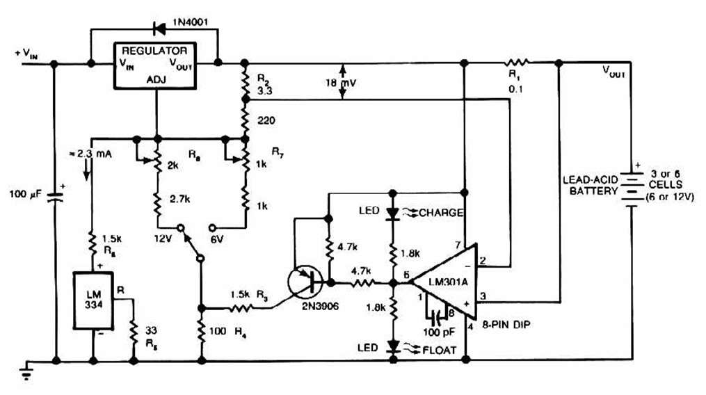
The schematic for this charger is straightforward. It is designed to charge a Gel Cell or other lead-acid types. This simple battery level monitor circuit can indicate the charging process in a 12 Volt lead-acid battery or tubular battery....
This is a silicon transistor circuit showing typical voltage values. When the forward base/emitter voltage is 0.6 to 0.7 V, the transistor is silicon. Germanium transistors will have a forward base/emitter bias voltage of 0.2 to 0.3 V. This...
This light-sensitive automatic light switch circuit is designed to be connected to the main 220V supply. The circuit will activate a 220V lamp during nighttime. The light-sensitive automatic light switch circuit operates by utilizing a light-dependent resistor (LDR) to detect...
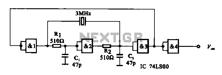
A crystal oscillator circuit is composed of several gates. Figure (A) illustrates a crystal oscillator circuit operating at 1 MHz, while Figure (B) depicts a 20 MHz crystal oscillator circuit. Figure (C) represents a variable crystal oscillator circuit with...