
Visible-Light Receiver Circuit
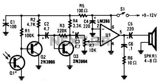
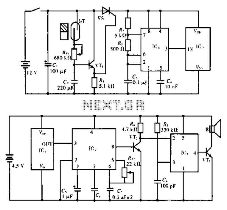
The described circuit operates by detecting amplitude-modulated light signals, which are typically generated by an infrared LED or similar light source. The phototransistor Q1 serves as the primary sensing element, converting the incoming light signals into electrical current. The parabolic reflector enhances the effective range by directing more light onto the phototransistor, thus improving sensitivity and performance in various lighting conditions.
The emitter-follower transistor Q2 is configured to provide impedance matching between the phototransistor and the subsequent amplifier stage. This configuration ensures that the output from Q1 can drive Q3 effectively, allowing for a stronger signal to be amplified. The amplifier Q3 is crucial for boosting the weak signals received from the phototransistor to a level suitable for processing.
Following amplification, the output signal is passed through a volume control resistor R7, allowing for user adjustment of the audio output level. This control is essential for tailoring the listening experience to the user's preference and ensuring that the audio signal is not too loud or too soft.
Finally, the audio amplifier U1 is responsible for driving the speaker or headphones, converting the amplified electrical signals into audible sound. The recommended power supply voltage range of 9 to 12 volts ensures that all components operate within their specified limits, providing reliable performance and longevity for the receiver circuit.
This circuit design is versatile and can be adapted for various applications, including wireless audio transmission systems, remote control devices, and other light-based communication systems. This receiver for amplitude-modulated light signals uses phototransistor Ql mounted in a parabolic reflector (to increase range). Any npn phototransistor should work. Emitter-follower Q2 drives amplifier Q3. The output from Q3 feeds volume control R7 and audio.amplifier Ul. A 9- to 12-V supply is recommended for the receiver. 🔗 External reference
Related Circuits
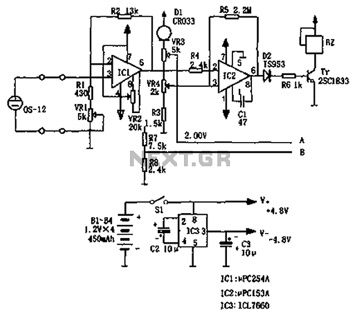
The circuit principle involves an oxygen sensor circuit utilizing the OS-12, a DC amplifier IC1, an A/D converter IC4, a liquid crystal display F2100-34PI, a voltage comparator IC2, and a positive and negative power converter IC, among other components....
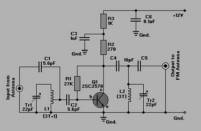
This is a simple circuit of an FM booster designed to enhance the reception of programs from distant FM stations. The amplifier effectively captures signals from far-off FM stations. The configuration is set up as a common-emitter tuned RF...
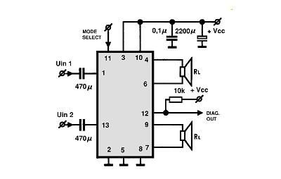
A simple Class B power amplifier can be constructed using the TDA8560 audio integrated circuit (IC). The TDA8560 amplifier features an internally fixed voltage gain, ensuring excellent channel balance. This audio amplifier project is capable of delivering dual 40-watt...
This circuit will allow you to connect any tape recorder that has a mic and remote input to a phone line and automatically record both sides of a conversation whenever the phone is in use. You will need to...
The alarm circuit is composed of two main components: the transmitter and the receiver. The transmitter circuit, as illustrated in Figure A, features a smoke break reed switch labeled GT. When a magnet approaches the GT, the internal contacts...
This circuit can be used for detecting infrared light; for example, it is utilized for detecting infrared band light signals in a spectrophotometer. The amplifier output voltage Vo is given by the formula Vo = Is·Rd·Rf/Ri, where Is is...
Warning: include(partials/cookie-banner.php): Failed to open stream: Permission denied in /var/www/html/nextgr/view-circuit.php on line 713
Warning: include(): Failed opening 'partials/cookie-banner.php' for inclusion (include_path='.:/usr/share/php') in /var/www/html/nextgr/view-circuit.php on line 713