
voltage Calculating current in a simple circuit
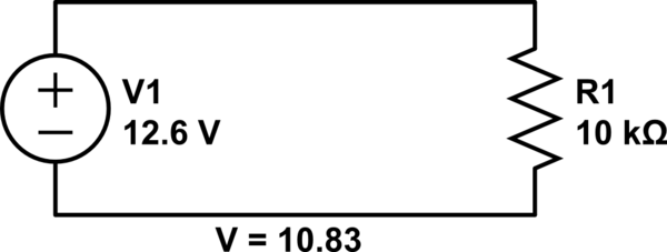
The circuit design includes a 12V power supply connected to a 12V fan that draws 70mA of current. The fan’s specifications dictate that the circuit must be capable of supplying this current consistently. A resistor is employed to ensure proper current limiting for any additional components, such as LEDs, that may be included in the circuit. The analysis of voltage drops across resistors is crucial for understanding potential issues with wiring or power supply performance.
When measuring the voltage across a resistor, it is essential to recognize that the reading reflects the voltage drop due to the current flowing through it. In this scenario, measuring 10.83V across a 10kΩ resistor indicates a current of approximately 1.83mA, which is acceptable for that resistor value. The voltage drop of 1.77V that is observed could be attributed to resistance in the wiring or a failing battery. It is advisable to calculate the total resistance in the circuit, considering the series resistance of the battery and the wiring, to ensure the circuit operates efficiently.
For the LED components, current limiting is critical to avoid exceeding their rated current. The use of a 330Ω resistor in series with each LED allows for a safe operating current of approximately 30mA, which is typical for many standard LEDs. This design choice not only ensures the longevity of the LEDs but also maintains adequate brightness levels. The choice of resistor wattage is also important; using a quarter-watt resistor is standard, but opting for a higher-rated resistor can provide additional safety and reliability in the circuit.
In summary, this circuit design effectively integrates a 12V fan and LED components while addressing critical factors such as current supply, voltage drops, and component safety, ensuring a reliable and functional electronic system.Attach a 12V fan to this circuit which draws 70mA (0. 007A), so the circuit must have at least that much current. Yes, there is something missing in the analysis. Actually there is too much in the analysis. The voltage drop across the resistor will be simply be the voltage you are putting across it, i. e. 12. 6V (or 12, 6 in your numeric language :) angelatlarge Apr 7 `13 at 4:30 The issue here is probably coming from the term "voltage drop". If you measure 10, 83 V at the resistor then your are either losing voltage to your cabling(probably not at 1ma) or you have a battery that is very near end of life and sagging a little. Your voltage "drop" on the resistor is how much the voltage changes across the resistor, not how much it changes getting their.
So 10, 83/10k is. 00183 A or 1. 83 mA, which is reasonable for a 10k resistor. Kortuk™ Apr 7 `13 at 4:47 so, for 1, 77V drop, that is happening in your cabling or battery, so if you take that drop with the current you re calculating you can determine the resistance of the cabling+series resistance of battery that is being placed with R1. I would write an answer, but someone with pictures would make a much better job then me. Kortuk™ Apr 7 `13 at 4:54 @angelatlarge, you are right. the voltage across the resistor will be the same as there is only one load, so the current will be I = V/R, I = 12.
6V / 10K = 1. 26mA. David Norman Apr 7 `13 at 5:19 @vsams14 I believe you might have some misconceptions about what voltage and current from a power supply are. this question is very detailed and might help you. If you are just asking if your power supply will work for this fan, if the fan is designed for a 12V supply you are 95% fine.
Kortuk™ Apr 7 `13 at 6:25 LEDs are current-based devices, not voltage based. In other words, the design parameter for a driving circuit is, how much current should be allowed to pass through an LED. This current limiting is frequently done by putting a resistor in series with the LED (one for each LED if several are to be used in parallel).
The current rating of the LEDs is not stated in the question. Since many common LEDs are typically rated for 20 or 30 mA, assuming 30 mA (0. 03 Amperes) for the purpose of this answer. The next higher commonly available resistor value of 330 Ohms would work well - Connecting one in series with each LED fed from the 12 Volt power rail should work fine. The higher than calculated resistor also increases the margin of safety by slightly reducing the current through the LED, without perceptibly reducing illumination.
This is pretty close to a quarter watt, one of the commonly used resistor power ratings. Therefore, for a margin of safety, a higher wattage resistor is suggested. 🔗 External reference
Related Circuits
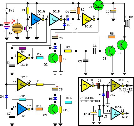
This circuit generates dual-tone bell sounds similar to those found in standard doorbell units. It is applicable in various contexts beyond doorbells. The circuit, as depicted in the diagram, produces a "Ding-tone" when switch P1 is pressed and a...
The circuit utilizes a 4-bit encoder to generate data, which is then modulated using an RF modulator for transmission. On the receiving end, the signal is demodulated, and a decoder retrieves the 4-bit data. The pin configuration for the...
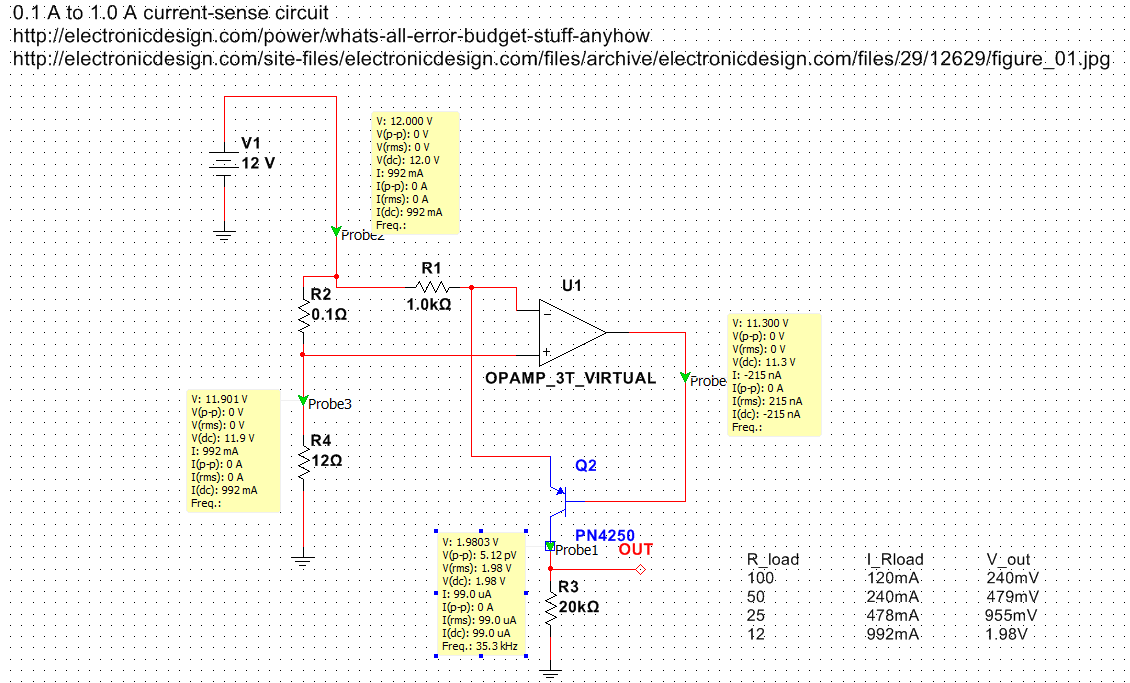
Exploring various methods for current sensing using standard operational amplifiers instead of specialized chips like the MAX4073T/F/H, which perform well but are relatively expensive. An article by Bob Pease discussing "error budgets" caught attention, particularly Figure Two of the...
A schematic diagram for a broadband QRP SWR metering circuit intended for use in a QRP antenna tuner. The circuit allows the user to press a momentary DPDT switch to observe an LED indicator while adjusting the capacitors of...
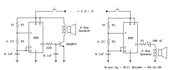
This is a basic 555 square wave oscillator used to produce a 1 kHz tone from an 8-ohm speaker. In the circuit on the left, the speaker is isolated from the oscillator by an NPN medium power transistor, which...
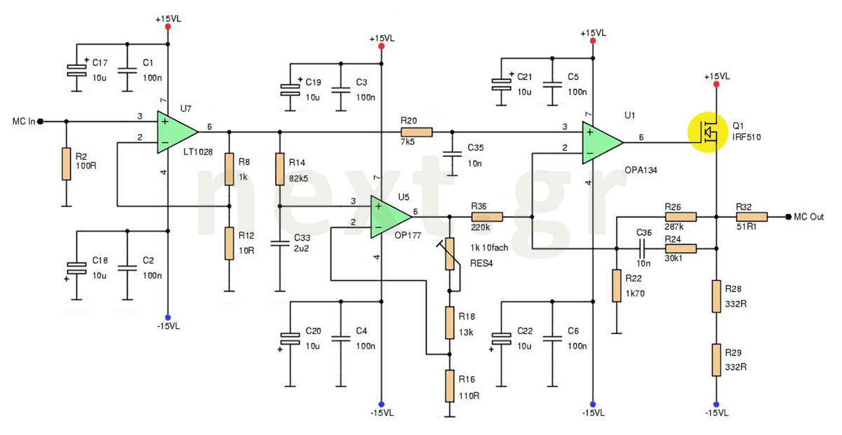
This microphone preamplifier circuit enhances the acoustic signal of a moving coil microphone (MC) with a sensitivity of 150μV at line level. In this design, a specific technique is not employed because the noise produced does not significantly impact...