
cable test
The Multi-core Cable Tracing System is an innovative solution designed to address the challenges of identifying and tracing multiple cables in complex environments. The Sender unit, capable of connecting to up to 64 wires, utilizes a unique pulse-width modulation technique to differentiate between the wires. This technique ensures that each wire receives a distinct pulse duration, which the Readout unit interprets to indicate the specific wire number.
The design incorporates a user-friendly interface, with the two-digit LED display providing clear visual feedback on the wire being traced. The battery-powered nature of both units enhances portability and convenience, making the system suitable for use in various locations without reliance on mains electricity. The inclusion of a battery status LED serves as a practical feature for maintaining operational readiness.
Safety is a paramount consideration in the design of this system. The explicit warning against using the system on live cables underscores the importance of ensuring that both ends of the cables are disconnected before initiating the tracing process. This precaution not only protects the integrity of the equipment but also safeguards the operator from potential electrical hazards.
The choice of components, such as the 74HC or 74AC logic devices, reflects a careful balance between performance and availability. The decision to utilize a single wire driving method minimizes complexity and enhances reliability, ensuring that the system operates effectively without the need for a common ground.
Overall, the Multi-core Cable Tracing System represents a significant advancement in cable management technology, providing a practical and efficient solution for tracing and identifying multiple cables in a variety of settings.Imagine being faced with a dozen or more cable ends, all the same colour and bearing no identification. The other ends emerge in another part of the building, and you have no way of knowing which is which.
You could use a continuity tester and a long length of wire to extend one of the probe leads. But if you had fifty wires, and a five minute walk from one end to the other, it would take you a good working day just to trace them all through! The Multi-core Cable Tracing System presented here is designed to make this sort job less of a nightmare! The Sender unit is connected to up to 64 wires at one end, and then the Readout unit is used to indicate which is which from the other end.
The Readout is simply connected to any two wires at the other end, and the display indicates which wire number the positive lead is connected to. Unlike some commercial systems, this system does not require a separate known common connection between the two units.
The two units are both battery powered, allowing them to be used in situations where mains power is not readily available. A red LED on each unit indicated that the battery is OK. If the LED does not light or is very faint, the battery should be replaced. PP3 batteries were used in the prototype, but for more regular use larger capacity 9V batteries would be a better choice, for example six AA cells in a suitable holder.
Low cost 9V plug-in mains adaptors could also be used. The 2 digit seven segment LED display on the readout unit is blanked whenever it is not connected to a cable, to conserve battery life. This system must never be used on live cables. Ensure both ends of the cables to be traced are disconnected before using this system. If in any doubt, check with a test meter. Connection to live cables will cause damage to this system, and could endanger the operator. With any cable tracing system, a different signal must be sent down each wire. The signal is then identified at the other end. Several systems were considered before deciding on the simple solution used here. An analogue system using differing voltage levels were ruled out, primarily because it would not work with my plan of having no specific ground wire between the two halves of the system.
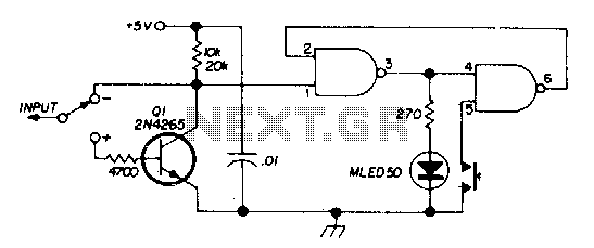
Noise pickup and voltage drops in long cables could also affect the results. I then considered a digital coding system, where a different serial code is sent down each wire. Although this would work well, it would result in a rather complex design. A system using differing frequencies was also considered, but again ruled out for reasons of complexity. I finally settled on a system that sends different length pulses along each wire. The receiver simply has to measure the pulse duration to determine which wire it is connected to. This has the advantage of being relatively straightforward and cheap. The only potential problem is that the capacitance of long cables might affect the pulse shape. By using logic devices with symmetrical outputs to drive the cable (74HC series logic), any pulse shaping distortion should occur equally on the rising and falling edges.
This works well in practice, providing the receiving device has a Schmitt trigger input. The clock frequency is fairly low, so any distortion in the pulse shape would have to fairly severe before the reading accuracy would be affected. If use with long cable lengths is likely, I would suggest using 74AC logic devices for the output drive.
74AC devices have an output drive of +/- 16mA compared to +/- 4mA for 74HC, so they should be less affected by capacitive loads. However they are not so readily available, and are typically two or three times the price of 74HC devices.
Only one wire is driven at a time. This is necessary to fulfill the requirement of not having a common ground wire. All output lines are normally high, and a low pulse appears on each wire in turn. The total time taken to cycle round all outputs is 🔗 External reference
Related Circuits
First of all you have to build one cable adapter to connect the female 9pins connector of the modem, with female 9pins connector of the base of E-10G HPC. To build the null modem cable you will need: 2...
There are two switches: a memory disable switch and a pulse polarity switch. The memory disable switch is a push-button that resets the memory to a low state when pressed. The pulse polarity switch is a toggle switch that...
Most telephone equipment today utilizes a DTMF receiver integrated circuit (IC). A widely used DTMF receiver IC is the Motorola MT8870, which is commonly found in electronic communication circuits. The MT8870 is an 18-pin IC employed in telephones and...
This project involves a straightforward soil moisture detection circuit that utilizes only four components and operates with a 3-volt battery. The circuit is designed to identify the presence of moisture in the soil of any plant and activate an...
A $35 teaching aid for basic electronics, and an invaluable experimental setup for the electronics hobbyist. It teaches basic analog and digital electronics. The teaching aid is designed to facilitate the understanding of fundamental concepts in both analog and digital...
A multi wire cable tester with a separate LED for each wire. Will show open circuits, short circuits, reversals, earth faults, continuity and all with four IC`s. Designed initially for my intercom, but can be used with alarm wiring,...