
Multi Wire Cable Tester

The multi-wire cable tester is an essential tool for diagnosing and ensuring the integrity of various types of wiring systems. This device utilizes a configuration of four integrated circuits (ICs) to monitor multiple wires simultaneously, providing a visual indication of their status through individual LEDs assigned to each wire.
The tester is capable of detecting several key conditions: open circuits, which indicate a break in the wire; short circuits, where unintended connections occur; wire reversals, which can happen in misconfigured connections; earth faults, which signify a connection to ground that should not exist; and continuity, confirming that the electrical path is intact. Each condition triggers a specific LED, allowing for quick visual diagnostics.
The design of the tester is versatile, making it suitable not only for intercom systems but also for alarm wiring and Ethernet cables such as CAT 5. The use of four ICs allows for efficient processing and monitoring of multiple wires at once, enhancing the tester's capability to provide accurate readings.
In terms of circuitry, the device likely includes a microcontroller or logic gates to interpret the signals from the wires and control the corresponding LEDs. Each wire's connection would be routed through a resistor to limit current and protect the LEDs from damage. The schematic would also include power supply connections to ensure the ICs operate within their specified voltage range.
Overall, this multi-wire cable tester represents a practical solution for both professional and amateur electricians, streamlining the process of cable testing and fault diagnosis in various applications.A multi wire cable tester with a separate LED for each wire. Will show open circuits, short circuits, reversals, earth faults, continuity and all with four IC`s. Designed initially for my intercom, but can be used with alarm wiring, CAT 5 cables and more. 🔗 External reference
Related Circuits

DC motors can be operated remotely using controls transmitted via an RF module. This circuit employs an RF module to manage DC motors through a motor driver integrated circuit (IC) L293D. Transmission is initiated by setting pin 14 (TE,...

This simple three-phase tester utilizes a small current thyristor as the main component for verifying the correct or incorrect sequence of the three phases, eliminating the need for an additional power supply. The basic circuit is depicted in Fig....
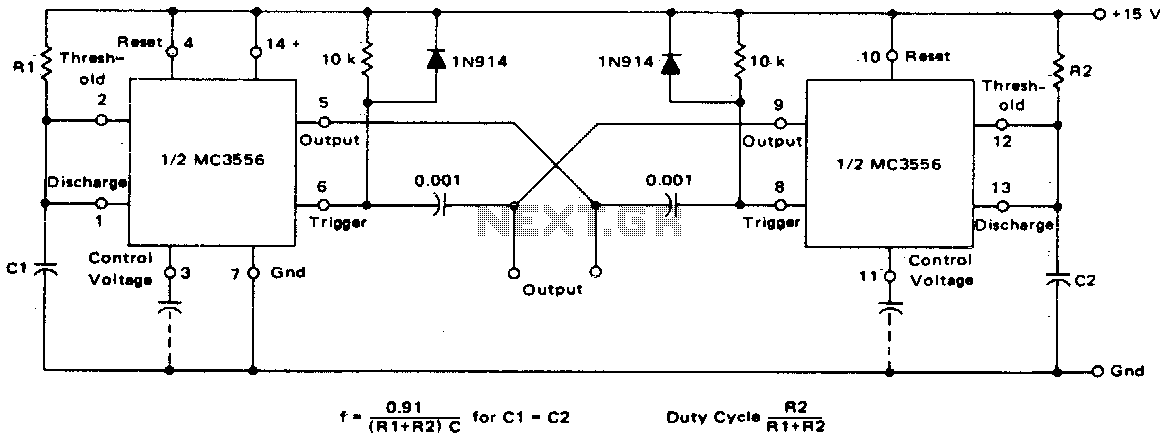
This dual astable multivibrator offers versatility not found in single timer circuits. The duty cycle can be adjusted from 5% to 95%. The two outputs generate two-phase clock signals, which are frequently required in digital systems. Additionally, it can...

This circuit utilizes a single 555 Timer IC along with a small transformer to generate high voltage for testing zener diodes with voltage ratings up to 50VDC. The 555 timer operates in astable mode, with the output from pin...

Camping today often requires carrying various electronic devices for daily activities and entertainment. Typically, a charged lead-acid battery and a power inverter are utilized to ensure a well-organized trip, allowing family members to use their electronic devices comfortably. It...

This document presents a simple schematic of a multitone siren alarm circuit. The multitone siren is effective for reverse horns, burglar alarms, and various other applications. It generates five distinct audio tones, making it significantly more attention-grabbing than a...