
Calculator-to-stopwatch converter

The circuit utilizes a 555 timer configured in monostable mode to create a stopwatch function. When the push-on switch is activated, the timer begins to run, generating a pulse at a predetermined frequency. This frequency can be adjusted by changing the resistor and capacitor values connected to the timer, allowing for precise timing intervals.
The output from the 555 timer can be used to drive a display, such as an LED or an LCD, to visually indicate the elapsed time. In addition, the circuit can incorporate a second push-off switch that, when activated, will stop the timer and reset the display to zero.
To ensure compatibility with various calculator batteries, the circuit should include a voltage regulator to maintain a stable voltage supply to the 555 timer and any additional components. Proper filtering capacitors should also be included to reduce noise and improve the reliability of the circuit.
Overall, this stopwatch circuit enhances the functionality of standard calculators, providing an additional tool for users while maintaining simplicity and ease of use.This circuit can be fitted to any calculator existing calculator battery via the push-on with an automatic constant to enable it to be push-off switch and the existing calculator on-used as a stop-watch The 555 timer is set to off switch, run at a suitable frequency and connected to the. 🔗 External reference
Related Circuits
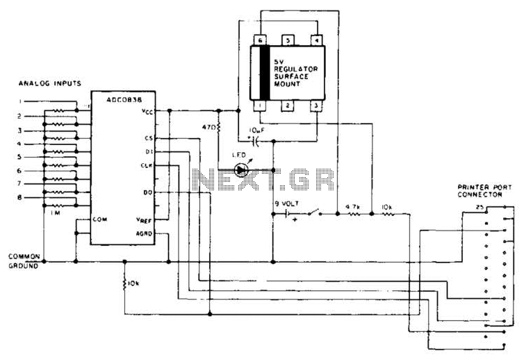
An A/D converter by National Semiconductor (ADC0838) converts 0 to 5 V analog inputs into a digital data format. A 9 V battery is utilized. The converter connects to the pointer port connector through a 25-pin connector. The ADC0838 is...
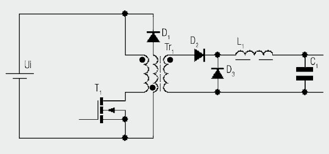
The diagram illustrates the basic construction of a forward converter. In contrast to the flyback converter, which temporarily stores energy before transferring it to the secondary side, the forward converter facilitates direct energy transfer between the primary and secondary...
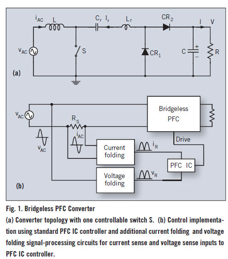
A bridgeless Power Factor Correction (PFC) converter utilizing an innovative switching method eliminates the need for full-bridge rectifiers, thereby reducing the size and cost of switching power supplies. The bridgeless PFC converter operates by directly converting the AC input voltage...
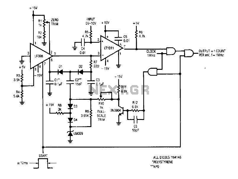
The simple 4-digit converter circuit has an output count of 1, designed for a frequency range from f-IMHz to 10.000 MHz. All diodes used in the circuit are IN4146 "POLYSTYRENE" NPO. The circuit utilizes the LF398 at the input...
The LT3465/LT3465A are step-up DC/DC converters designed to drive up to six LEDs in series from a Li-Ion cell. Series connection of the LEDs provides identical LED currents and eliminates the need for ballast resistors. These devices integrate the...
The circuit diagram illustrates two LT1398 operational amplifiers from Linear Technology utilized to generate buffered color-difference signals from RGB (red-green-blue) inputs. In this setup, the R input is received through a 75-ohm coaxial cable and directed to the non-inverting...