
Analogue to digital converter circuit

The described 4-digit converter circuit operates as a frequency counter, capable of accurately measuring and displaying frequencies within the specified range. The LF398, a precision analog-to-digital converter (ADC), serves as the input component, converting the analog frequency signal into a digital representation. The LF398 is known for its high-speed performance and low power consumption, making it suitable for applications where rapid and efficient frequency counting is required.
The choice of IN4146 diodes, recognized for their low leakage current and high-speed switching capabilities, enhances the circuit's performance by ensuring minimal signal distortion and maintaining signal integrity. The use of "POLYSTYRENE" NPO capacitors in the design further contributes to the stability and accuracy of the circuit, as these capacitors exhibit low dielectric losses and excellent temperature stability.
The output count of 1 indicates that the circuit provides a single digital output, which can be interfaced with a display module or microcontroller for real-time frequency readouts. The overall design is optimized for simplicity, reliability, and precision, making it suitable for various applications in telecommunications, signal processing, and laboratory measurements. The circuit can be further enhanced by incorporating additional features, such as averaging or filtering, to improve measurement accuracy in noisy environments.That simple 4 digits converter circuit has OUTPUT COUNT = 1 according to my f-IMHz to 10.000. All diodes are IN4146 "POLYSTYRENE" NPO. The circuit uses the LF398 at input.
Related Circuits
This circuit measures the distance covered during a walk. The hardware is housed in a small box that can be slipped into a pants pocket, with the display designed as follows: the leftmost display D2 (the most significant digit)...
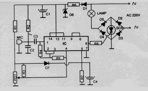
This disco lamp circuit is not a voice-operated switch (VOX) because it cannot differentiate between musical sounds and human voices. Instead, it is sound-activated. An interesting application of this circuit is to control disco lighting automatically using the musical...

The multi-purpose signal generator circuit consists of integrated circuit oscillators and frequency dividers. It generates square waves ranging from high frequencies to sub-audio frequencies and also produces a frequency standard in the VHF range. The alternative oscillator section feeds...
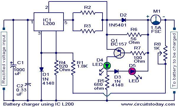
A simple battery charger circuit with reverse polarity indication is presented here. The circuit utilizes the L200 integrated circuit (IC), which is a five-pin variable voltage regulator. The charging circuit can be powered by DC voltage from either a...
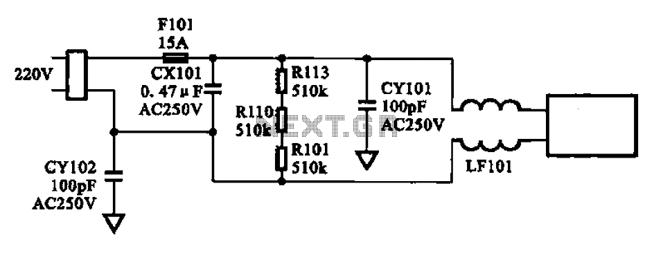
The AC input circuit consists of a fuse (Fl01), a mutual inductance filter (LF101), and filter capacitors (CX101, CY101, CY102), among other components. Its primary function is to filter out noise and pulse interference from the AC circuit, as...
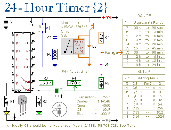
These two circuits are multi-range timers that offer periods of up to 24 hours and beyond. They can function as repeating timers or single-shot timers. Both circuits are fundamentally the same, with the primary distinction being their behavior in...