
To simulate the Gyralite (dual flashing headlights).
The circuit described is designed to operate from a 5-volt DC power supply, which is a common voltage level for many electronic applications. The circuit may include a flashing LED, which serves as an indicator or decorative element, particularly suitable for model trains or locomotives.
To construct the circuit, a reliable 5-volt DC source should be selected, which can be derived from various power supplies such as voltage regulators, battery packs, or USB power adapters. The power source must be capable of delivering sufficient current for the components in the circuit, especially if multiple LEDs or other devices are used.
The optional flashing LED can be implemented using a simple astable multivibrator circuit, which can be constructed with a 555 timer IC. The 555 timer can be configured to produce a square wave output, causing the LED to turn on and off at a specified rate. The frequency of the flashing can be adjusted by changing the resistor and capacitor values in the timer circuit.
For the LED itself, it is important to include a current-limiting resistor in series with the LED to prevent excess current from damaging it. The value of this resistor can be calculated using Ohm's law, taking into account the forward voltage drop of the LED and the supply voltage.
Overall, this circuit provides a simple yet effective means of adding visual appeal to a model locomotive while ensuring compatibility with standard 5-volt power supplies.This circuit must be connected to a 5 volt DC source. See my RR page for several 5 volt supplies. Note the flashing LED is optional, but looks s-o-o-o-o good on the top of a locomotive. 🔗 External reference
Related Circuits

When power is applied to the circuit, all Red LEDs will flash on and off simultaneously. The Yellow LEDs will also flash, but only every other Yellow LED will be illuminated at any given time. The Green LEDs will...
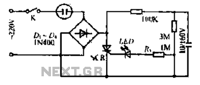
20V child-friendly power supply circuit for a foreign vine wine light, including a bulb and plug. The circuit features a bridge rectifier. The lamp access point is designed for a 10-100W bulb with a compact size. The output is...
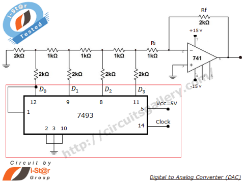
A Digital to Analog Converter (DAC) is utilized to produce an analog voltage that corresponds to input digital data. Binary data can be transformed into its analog equivalent using an R-2R ladder network combined with a summing amplifier, which...

6502 fully simulated at the transistor level. The simulator can be run in your browser. They are also taking submissions for other ICs to model. The 6502 microprocessor, originally designed by MOS Technology, is a popular 8-bit CPU known for...
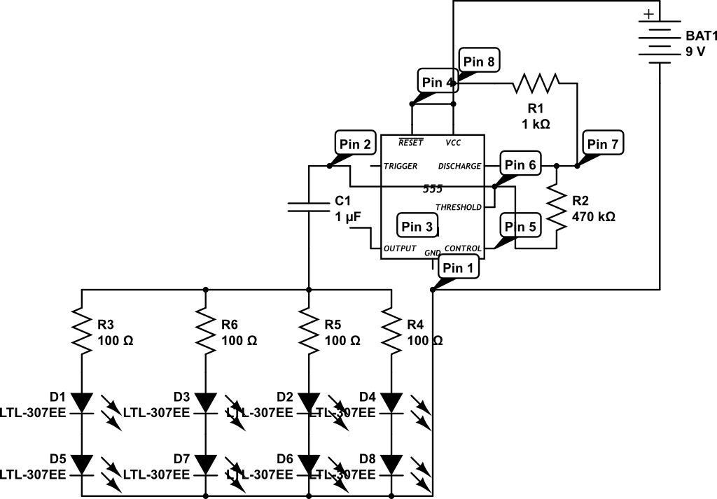
LEDs are rated for a continuous current of only 30 mA, while this circuit operates them at approximately 50 mA. Although this is acceptable for low duty cycles with short pulses, the intended design has a high duty cycle....
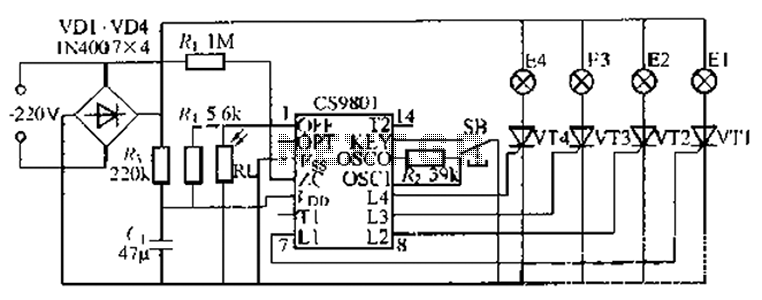
The ASIC is a flashing light string controller featuring four outputs. It includes a single key cycle control with six different lighting effects, and it allows for the selection of either 16 or 8 patterns. The circuit incorporates a...