
Camera power supply circuit
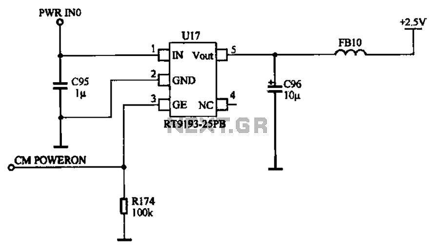
The camera power supply circuit is critical for ensuring that the camera operates effectively and reliably. It typically consists of various components designed to regulate the voltage and current supplied to the camera. A stable voltage control integrated circuit serves as the core of this power supply, providing a consistent output voltage that meets the camera's operational requirements.
The circuit may include input capacitors that filter incoming voltage to remove noise and transients, ensuring a clean power supply. Additionally, a rectifier may be employed to convert AC voltage to DC voltage, which is essential for most camera systems. The output of the rectifier is then smoothed using filter capacitors to minimize ripple voltage, further stabilizing the power supply.
The integrated circuit used in the power supply may feature built-in protection mechanisms such as over-voltage protection, thermal shutdown, and short-circuit protection to enhance the reliability of the camera. The output voltage is typically adjustable, allowing for compatibility with various camera models that may have differing voltage requirements.
Furthermore, the circuit design may include feedback mechanisms that monitor the output voltage and adjust the control signal to the integrated circuit, ensuring that the output remains within specified limits despite variations in load or input voltage. This feedback loop is essential for maintaining the stability of the power supply under different operating conditions.
In summary, the camera power supply circuit is a well-engineered assembly that guarantees the delivery of reliable power to the camera, utilizing a combination of integrated circuits, passive components, and protective features to ensure optimal performance and longevity of the camera system. Camera power supply circuit Shows the camera power supply circuit, the normal power supply in order to make the camera work properly, the power supply circuit is composed of a stable pressure control integrated circuit constituted.
Related Circuits
A schematic diagram of the high-voltage power supply recommended for use with the power transformer. This power supply can also be used for other equipment with similar requirements. CAUTION: hazardous high voltages. The high-voltage power supply schematic is designed to...
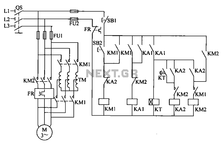
To initiate the system, turn off the power switch, then press the start button SB2. The KM1 contactor is energized, engaging self-locking, and closing the main contacts. The autotransformer TM is connected between the power source and the motor,...
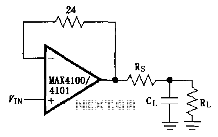
The MAX4100/4101 operational amplifiers utilize a capacitive load drive circuit with an isolation resistor Rs. The MAX4100 and MAX4101 can handle maximum capacitive loads of 5pF and 20pF, respectively, but are susceptible to overshoot and ringing oscillations. To mitigate...
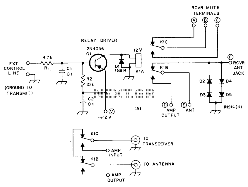
R1 and R2 are carbon composition resistors labeled as Va or Vi. K1 is a 12 V DPDT DIP relay. Illustration A demonstrates the connection of the relay contacts for use with a separate transmitter-receiver combination. The circuit is...
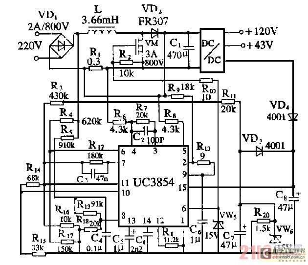
Improve the power factor (PF) to enhance energy conservation in electrical equipment. With advancements in electronic technology, high-frequency active power factor correction (PFC) technology has been increasingly applied across various power systems. The switching power supply of large-screen color...
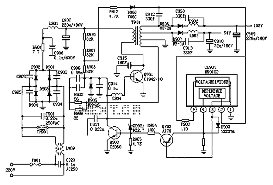
The Hitachi NP8C switching power supply circuit is illustrated in FIG. The Hitachi NP8C power models include CTP236, CEP320D, CRP350D, 450D, Furi HFC-236, 450, and Venus C37-401, C46-1, C563, among others. This circuit was widely used in early Chinese...