
Hitachi np8c switching power supply circuit diagram
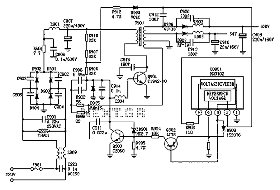
The Hitachi NP8C switching power supply circuit functions as a self-oscillating converter, utilizing a feedback mechanism to maintain stability in its output voltage. The operation begins with the application of a high voltage to the base of Q901, which acts as a switching element. The transformer T901 plays a critical role in energy transfer, converting the input voltage to the required output levels through its windings. The feedback loop, involving resistors and capacitors, ensures that any fluctuations in output voltage are corrected by adjusting the conduction levels of Q902 and Q903, which are responsible for regulating the overall power supply performance.
The use of diodes D906 and D907 in the circuit is essential for directing the current flow during different phases of operation, facilitating energy storage and discharge processes. The capacitors, particularly C908, are crucial for smoothing out voltage spikes and maintaining steady voltage levels during the oscillation cycles. The design of the regulator circuit allows for fine-tuning of the output voltage, which is necessary for compatibility with various load conditions.
In summary, the Hitachi NP8C switching power supply circuit is a well-engineered solution for converting and regulating power, utilizing a combination of feedback mechanisms, energy storage components, and control elements to achieve stable and efficient performance in early color television applications. As shown in FIG Hitachi np8c switching power supply circuit, Hitachi NP8C power models are: Hitachi CTP236, CEP320D, CRP350D, 450D, Furi HFC-236,450, Venus C37-401, C46-1, C563 , etc., the Chinas color TV power supply in the early and wide application. Oscillation 300V DC voltage by R911, R907, R908 is added to the B pole switch Q901, Q901 begins to conduct, T901 primary winding current starts to flow through, while the induced voltage on the positive polarity is negative, so this winding also induced voltage, with positive and negative polarity is lower, the voltage through R902, R909, C908 to Q901 B pole, so that further Q901 is turned on, a strong positive feedback Q901 rapid saturation. During Q901 saturated, D906, D907 off, T901 stored energy, while the positive feedback voltage to the C908 constantly charged with the C908 has been continuously charged, Q901 B-voltage falling, can not be maintained until saturation Q901, Q901 will be out of saturation.
Q901 Once out of saturation, T901 each winding induced voltage polarity reversal of all, but also a strong positive feedback Q901 rapidly closing. During Q901 off, D906, D907 conduction, based on the C909, C910 108V and 54V DC voltage, and turned D905, C908 through R902, R909, T901 feedback windings discharge circuit, at the same time, 300V voltage by R911, R907, R908 reverse charging to C908, so B voltage Q901 continues to rise until the Q901 is turned on again, then go to the next oscillation.
Regulator circuit Regulator circuit consists CP901, Q902, Q903 composition. CP901 (4) feet for the Q902s E pole reference voltage, the size of the output voltage can affect the level of conduction of Q902, Q903 thus affecting the conductivity of the same level, which can control the oscillation frequency Q901, also stabilized output voltage size. In addition, Q901 oscillation frequency is also affected by the line frequency control, the right line flyback pulse C912 introduced by the line frequency to control the oscillation frequency of the Q901, it is possible to obtain a stable output voltage.
Related Circuits

The circuit is designed to regulate a dual power supply that provides +12V and -12V from the AC mains. Such a power supply is an essential tool for an electronic hobbyist's workbench. The schematic of the circuit includes components...
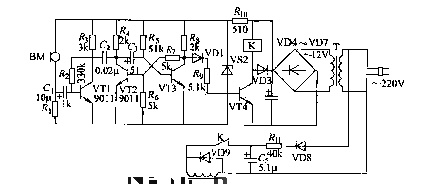
Cook in advance to open the door with a coal stove; before using the fire, it should be strong. This is an automatic door opening device that can automatically open the door before the regular homeowner, eliminating the need...
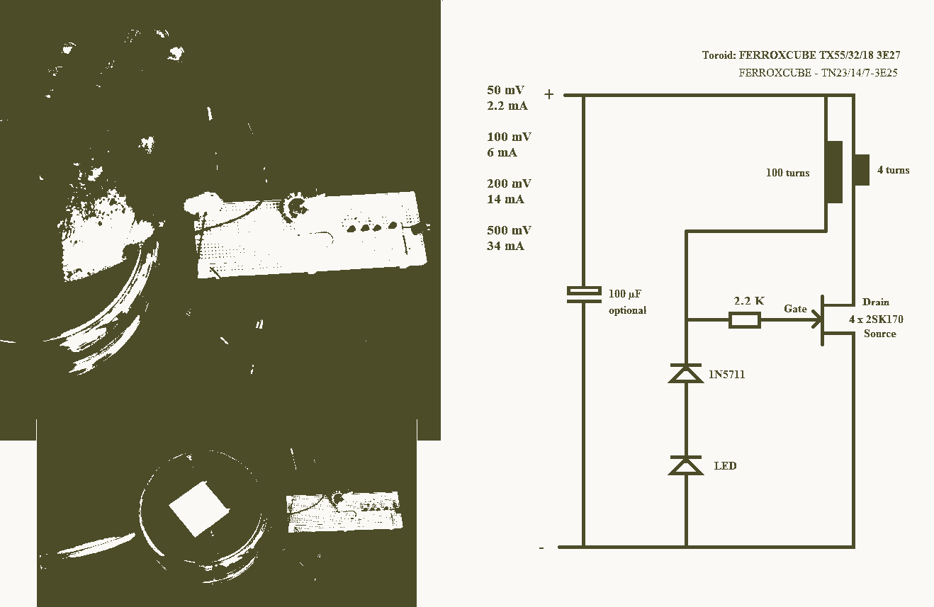
A 25mV Joule Thief powered by a Peltier device that utilizes body heat. The 25mV Joule Thief circuit is an innovative energy harvesting solution that converts the minimal voltage generated by a Peltier device into usable electrical energy. The Joule...
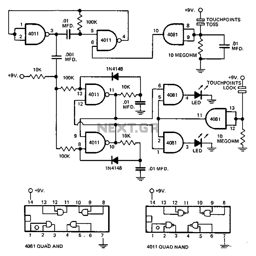
This circuit employs an astable multivibrator to alter the state of a signal based on specific conditions. It also incorporates a flip-flop, which retains the state of the output once a change is detected, completing a cycle of the...
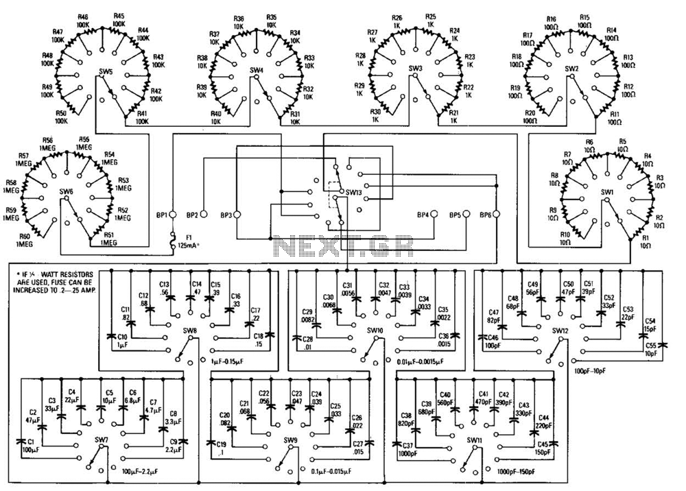
This decade box can be configured for any resistance value between 10 and 11.1 in 10-stop increments. A switch is employed to set various RC configurations. It is recommended to utilize precision components in the circuit. If feasible, verify...
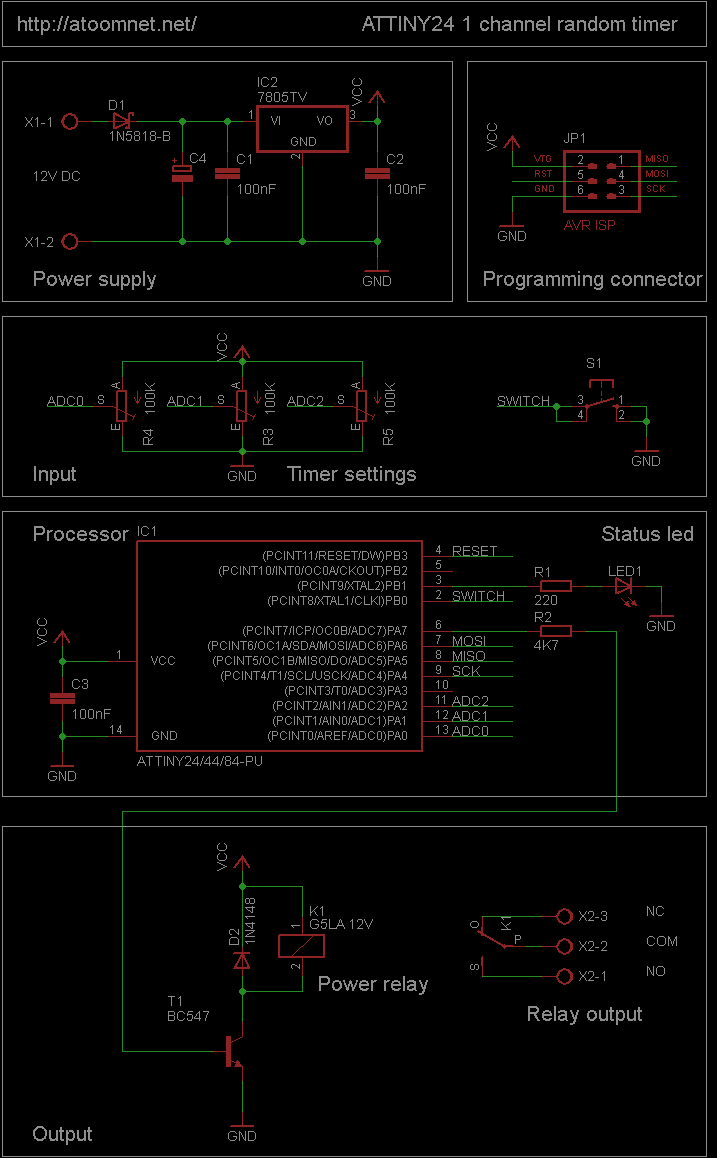
This random timer circuit is based on an Atmel ATTINY24 AVR driving one power relay. It can be used to switch on and off other circuits randomly. For instance, in a model railroad setup, this circuit can activate and...