
Capacitance compensation circuit diagram of a power protection
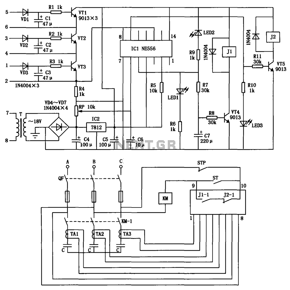
This circuit serves a critical role in safeguarding electronic components by monitoring voltage levels and ensuring they remain within specified limits. It typically employs a voltage sensing mechanism, which may consist of a voltage divider and a comparator. The voltage divider scales down the input voltage to a manageable level, while the comparator compares this scaled voltage against a predetermined reference voltage.
When the input voltage exceeds the reference level, the comparator triggers a response, which may involve activating a relay or a solid-state switch to disconnect the load from the power supply. This disconnection occurs swiftly to prevent damage to sensitive components, particularly power capacitors, which can be adversely affected by excessive voltage.
In addition, the circuit may include transient voltage suppression devices, such as varistors or TVS diodes, to absorb voltage spikes and provide an additional layer of protection. The design should ensure that the components selected can handle the maximum expected voltage and current levels, while also considering thermal management to avoid overheating during operation.
Furthermore, the circuit layout should minimize parasitic inductance and capacitance to enhance response time and reliability. Proper grounding techniques and isolation methods should be employed to prevent noise interference and ensure stable operation. Overall, the implementation of this over-voltage protection circuit is essential for maintaining the longevity and reliability of power supply systems in various electronic applications. Circuit is shown, it is used in the power supply circuit can occur in the case of over-voltage grid on or off phase, promptly cut off the power supply to protect power capacito rs.
Related Circuits
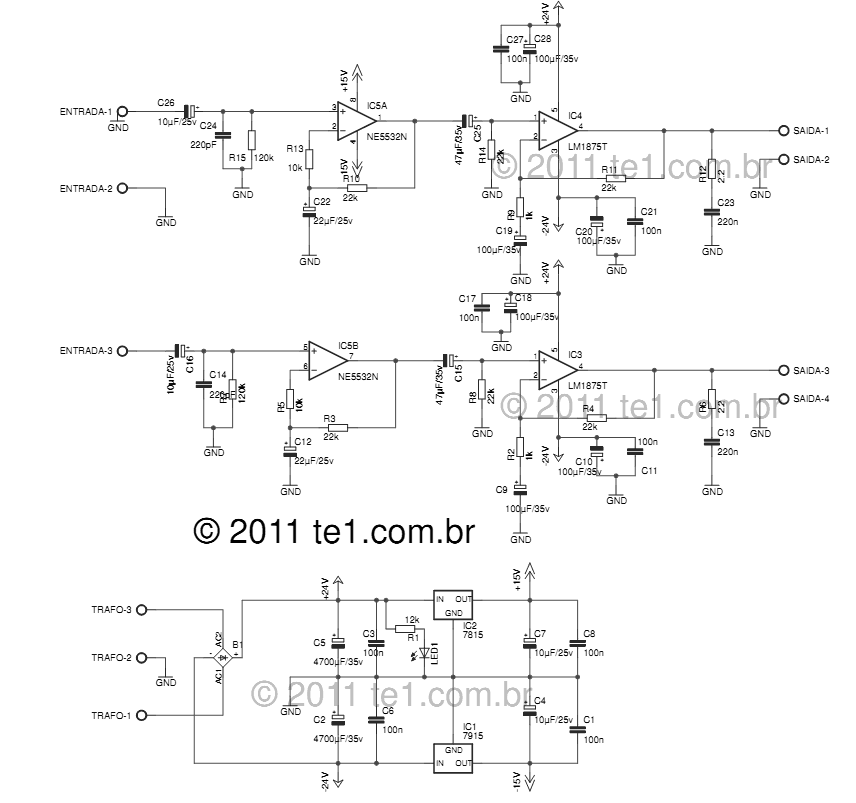
The LM1875 delivers 20 watts into a 4 or 8-ohm load on ±25V supplies. Using an 8-ohm load and ±30V supplies, over 30 watts of power may be delivered. The amplifier is designed to operate with a minimum of...
The circuit integrates several functions, including a smooth startup for the AC power line, with a one-second delay before connecting to the power supply transformers of the amplifier through relay RL1 and resistor Rx. This delay is designed to...
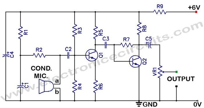
There is often a need for a sensitive sound pickup device, which can be utilized as a simple microphone or for more specialized applications such as a sound-operated alarm, a bugging device, or a sound-triggered flash for stop-action photography....
The fundamental principle of the theremin is the heterodyne oscillator. In the development of the Open Theremin, a stable and reliable oscillator was essential. Various schematics featuring different components were researched and constructed on small boards, which were then...
Siren Circuit. This circuit generates a sound siren when switch S1 is pressed, increasing the sound frequency as capacitor C1 charges. The sound frequency decreases when switch S1 is released. The siren circuit operates based on the charging and discharging...
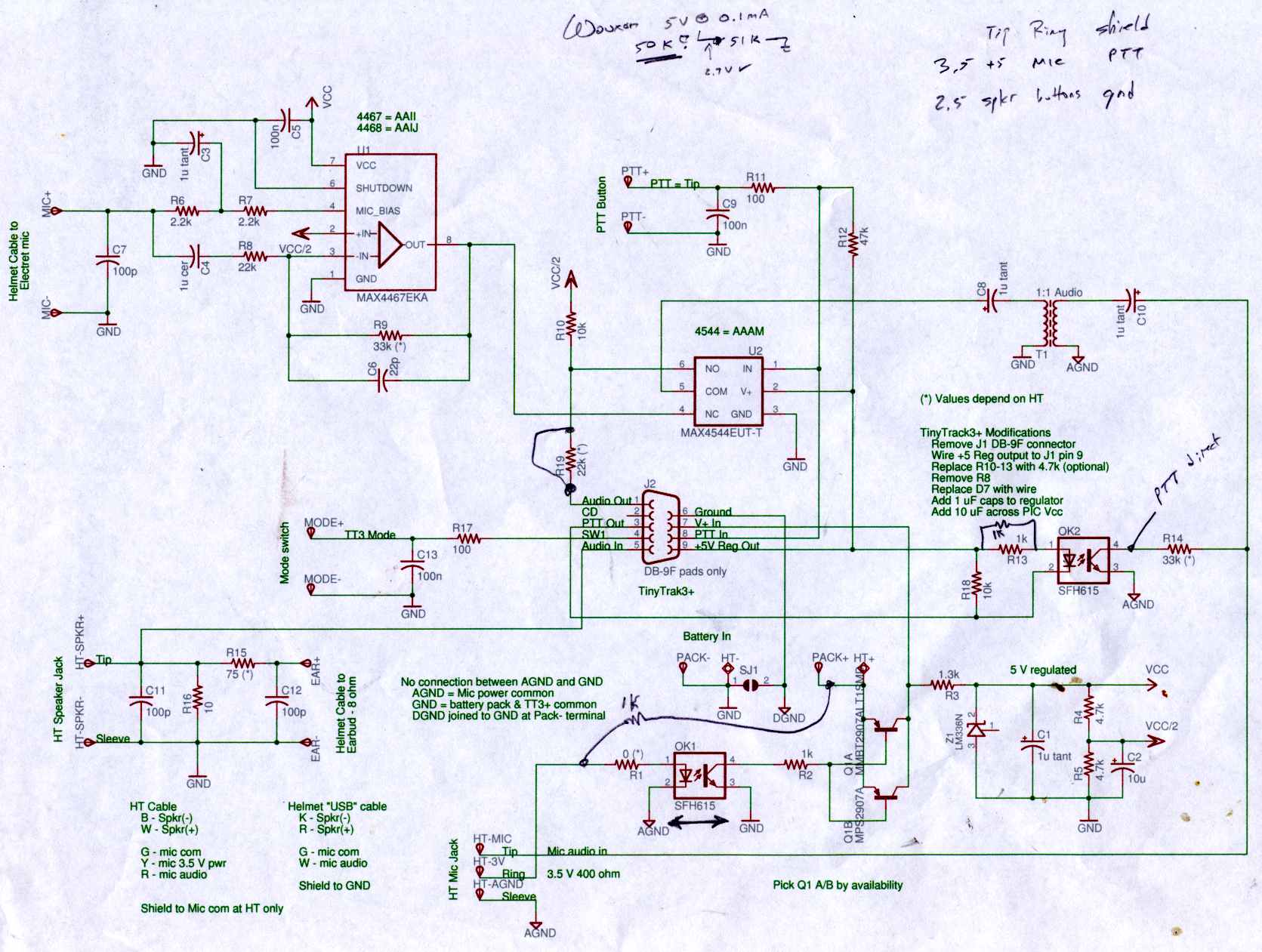
Connect the Byonics TinyTrak 3+ GPS modem, helmet earbud/mic, and external battery pack to the Z-1A, which is incompatible with the Wouxun. The KG-UV3D utilizes the Kenwood HT interface with a single ground for mic, speaker, and PTT functions,...
Warning: include(partials/cookie-banner.php): Failed to open stream: Permission denied in /var/www/html/nextgr/view-circuit.php on line 713
Warning: include(): Failed opening 'partials/cookie-banner.php' for inclusion (include_path='.:/usr/share/php') in /var/www/html/nextgr/view-circuit.php on line 713