
Siren Circuit
The siren circuit operates based on the charging and discharging characteristics of capacitor C1, coupled with a sound-generating component, typically a piezoelectric speaker or buzzer. When switch S1 is pressed, it completes the circuit, allowing current to flow and charging capacitor C1. As C1 charges, the voltage across it rises, which in turn affects the frequency of oscillation in the circuit. The frequency increases, producing a higher-pitched sound from the speaker.
The circuit may utilize a simple oscillator configuration, such as a 555 timer in astable mode, to generate the sound output. In this configuration, the charging time of C1, determined by the resistor values in the circuit, influences the frequency of the output waveform. As C1 charges, the time period for the output waveform shortens, resulting in a higher frequency sound.
Upon releasing switch S1, the capacitor begins to discharge, leading to a decrease in voltage and a corresponding reduction in frequency, producing a lower-pitched sound. The transition between high and low frequencies creates a siren-like effect, which can be used for alarms or alerts.
To enhance the circuit, additional components such as variable resistors can be incorporated to allow for frequency adjustment, or a diode can be added to control the discharge path of C1, thereby influencing the decay rate of the sound. Proper component selection and values are crucial for achieving the desired siren effects and ensuring stable operation of the circuit.Siren Circuit. This circuit is to generate sound siren when S1 is pressed and increate sound frequency because charged C1, S1 is released when the frequency decreated. 🔗 External reference
Related Circuits

The circuit below is a simple dimmer circuit. A network consisting of R1, R2, VR1, C2, C3, and Q1 controls the triggering angle of the triac by adjusting the variable resistor VR1. The described dimmer circuit employs a TRIAC (Q1)...

The circuit serves as a signal source for calibration level meters or sensor-driven differential transformers. The oscillation frequency is determined by the 74HC04, producing a frequency of 1 kHz through resistor R. The supply voltage of the circuit changes...
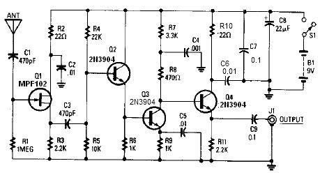
A simple active antenna can be designed using this electronic circuit diagram. This active antenna utilizes transistors and a few common electronic components. In the practice of short-wave frequency reception, a general rule is that a longer antenna will...
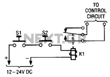
The simple two-hand safety control switch consists of two pushbutton switches connected in series; both must be depressed to energize the relay. The two-hand safety control switch is designed to enhance safety in applications where the operation of machinery or...
The Air Flow Sensor Circuit describes sensing air flow using the microcontroller PIC16C781. Air flow is detected by the cooling effect of air. The Air Flow Sensor Circuit utilizes the PIC16C781 microcontroller to effectively measure air flow by leveraging the...
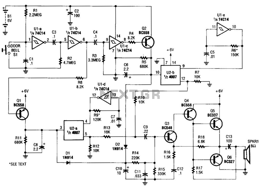
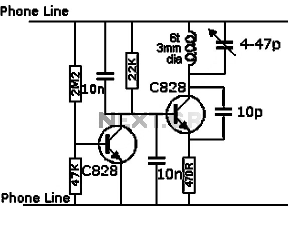
When the doorbell switch is pressed, two monostable stages are sequentially activated, applying bias to a pair of voltage-controlled resistor stages. These stages modulate the outputs from a pair of tone generators. The resulting signals are then fed to...