
CAPACITANCE METER
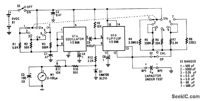
The circuit consists of two main functional blocks: the oscillator (U1a) and the measurement unit (U1b). The oscillator generates a continuous waveform, typically a square wave, which is modulated in width based on the capacitance being measured. This modulation occurs through a feedback mechanism that adjusts the duty cycle of the output signal relative to the capacitance value.
U1b, the measurement section, is responsible for interpreting the modulated signal generated by U1a. It employs a pulse-width modulation (PWM) technique to convert the varying width of the pulses into a voltage signal that can be easily read by the meter. The linearity of the meter ensures that the average voltage output is a direct representation of the capacitance value. This is particularly important for applications requiring precise capacitance measurements, as it allows for straightforward calibration and interpretation of results.
Meter M1 is designed to capture the average voltage of the PWM signal, which reflects the duty cycle of the output from U1a. Due to its mechanical frequency response characteristics, M1 is optimized to provide accurate readings at lower frequencies, making it suitable for this application. The overall design ensures that the circuit can effectively measure unknown capacitance values with a high degree of accuracy, leveraging the relationship between pulse width and capacitance to deliver reliable results.
In summary, this circuit design effectively integrates an oscillator and a measurement unit to facilitate the conversion of unknown capacitance into a readable voltage signal, allowing for practical and efficient capacitance measurement in various electronic applications.U1a is an oscillator and U1b the measurement part of the circuit. It converts unknown capacity into a pulse-width modulated signal the same way an automotive dwell meter works. The meter is linear so the fraction or percentage of time that the output is high is directly proportional to the unknown capacitance (CX in the schematic).
Meter M1 reads the average voltage of those pulses since its mechanical frequency response is low compared to the oscillator frequency of U1a. 🔗 External reference
Related Circuits
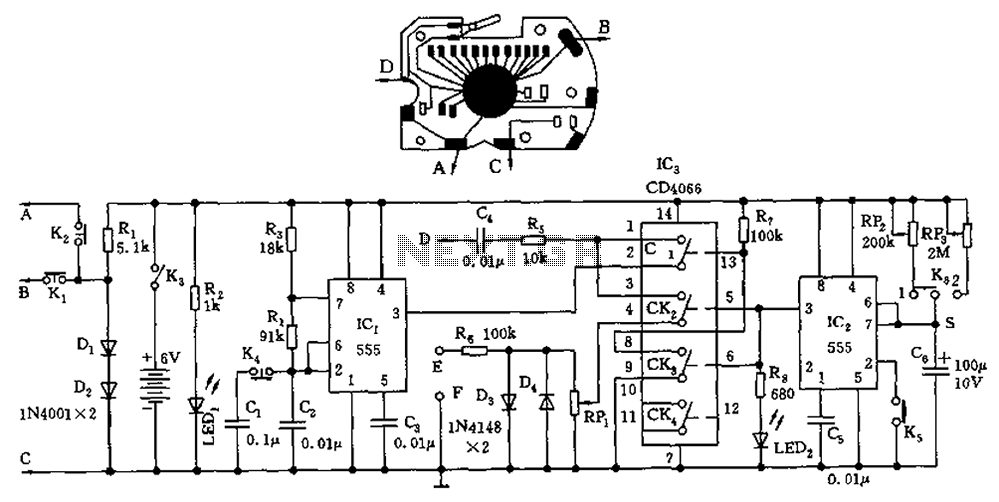
A circuit utilizing a standard digital quartz electronic watch, with its crystal soldered, forms a digital frequency meter as illustrated by the connected circuit. The test signal is applied to the E and F sides via components such as...
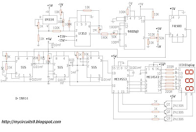
This circuit consists of a temperature sensor, amplifier, voltage-to-frequency (V/F) converter, a three-digit binary coded decimal (BCD) counter, a time base, and seven-segment LED displays. In addition to the 9400 V/F converter, other integrated circuits (ICs) required for this...
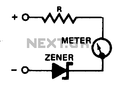
A zener diode placed in series with a voltmeter will prevent the meter from reading until the applied voltage exceeds the zener voltage. Thus, a 10-volt zener in series with a 5-volt meter will allow the condition of a...
The LM3915 is a monolithic integrated circuit that senses analog voltage levels and drives ten LEDs providing a logarithmic 3 dB/step analog display. LED current drive is regulated and programmable, eliminating the need for current limiting resistors. The IC...
Its based on inductive pickup and very easy to install. Have a look at the pic. (remove LED and connect transistor collector to pin4). I hope it will exactly suits to your tachometer. More: I found your PIC project...
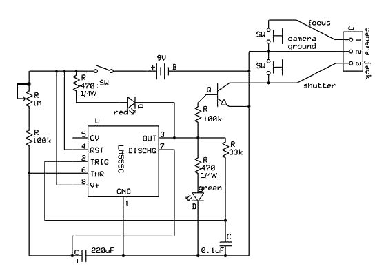
This instructable began with a previous camera hack that involved creating a remote shutter release. A tutorial on the 555 timer was discovered, highlighting its potential applications. The project centers around utilizing the 555 timer integrated circuit (IC) to develop...