
Bike LED Tachometer

The described circuit utilizes an inductive pickup method to detect the rotational speed of a motorcycle's engine, which is a common approach for tachometers. The inductive pickup sensor operates by generating a voltage signal in response to the changing magnetic field produced by the engine's ignition system or a rotating component. This signal can then be processed to provide an accurate reading of the engine RPM.
The installation process is straightforward, making it accessible for users with basic electronics knowledge. It is suggested to refer to a visual representation of the circuit, as indicated by the mention of a picture. The reference to removing an LED and connecting the transistor collector to pin 4 of a microcontroller implies that the circuit is designed to interface with a PIC microcontroller. This microcontroller will likely be responsible for processing the signal from the inductive pickup to calculate the RPM and display it on a connected output device.
The connection of the transistor collector to pin 4 indicates that this pin may serve as a digital input for the microcontroller, where the signal from the inductive pickup is read. This configuration allows the microcontroller to detect the voltage changes corresponding to the engine's rotational speed. Additional components, such as resistors and capacitors, may be necessary to condition the signal for optimal performance and to protect the microcontroller from voltage spikes.
It is important to ensure that the signal wire is correctly connected to the automotive system. This typically involves identifying the appropriate ignition coil or other relevant components where the inductive pickup can be installed to accurately sense the engine's activity. Proper installation and calibration are crucial for achieving reliable readings on the tachometer, which can enhance the motorcycle's performance monitoring and provide valuable feedback to the rider.Its based on inductive pickup and very easy to install. Have a look at the pic. (remove LED and connect transistor collector to pin4). I hope it will exactly suits to your tachometer. I found your PIC project collection very nice. I have been working on tachometer for my motorcycle. In your article you said that you don't know how to connect the signal wire to automotive. 🔗 External reference
Related Circuits

This power supply circuit is designed around a standard 12VAC landscape lighting transformer. The availability and selection of transformers have long posed challenges for experimenters, often leading them to use potentially hazardous off-line capacitor-limited power supplies. However, the widely...
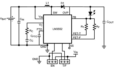
For this LED driver electronic project, a DC power supply circuit is required to provide an output voltage between 2.7V and 5.5V. The supply voltage must be applied between Vin and GND. The T/F jumper connects the T post...
All LEDs require some form of current limiting. Connecting an LED directly to the power supply will burn it out almost instantly. Overdriving, even briefly, will significantly reduce its lifespan and light output. Fortunately, driving a single or a...
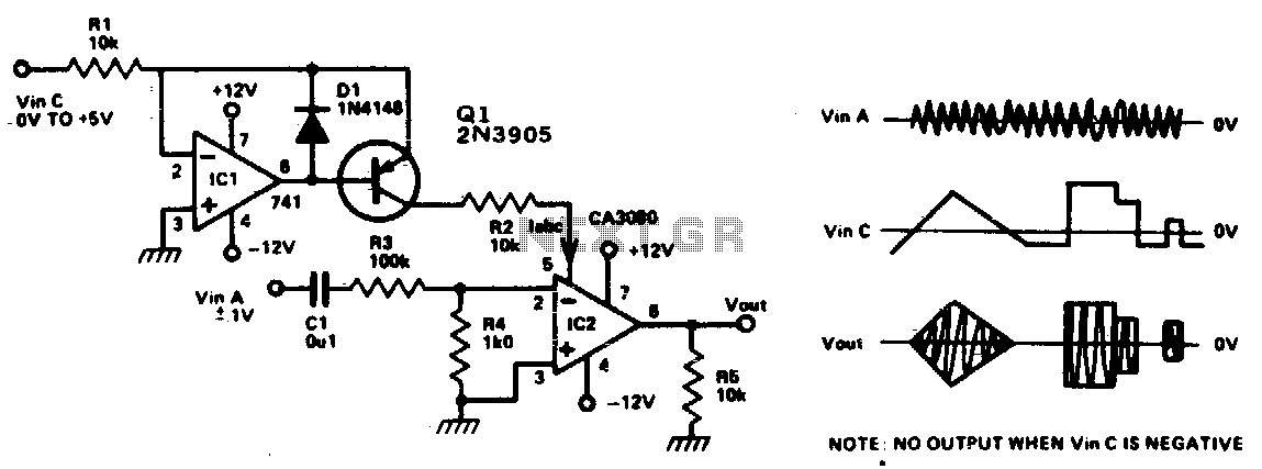
This circuit is essentially an operational amplifier (op-amp) with a differential input voltage of ±10 mV between pins 2 and 3, along with an additional input at pin 5. A current (Iabc) is injected to control the current at...
The circuit utilizes two quad voltage comparators (LM339) to illuminate a series of eight LEDs that indicate volume levels. Each of the eight comparators is biased at progressively higher voltages established by a voltage divider, allowing the lower right...
This is a low-power voltmeter circuit suitable for alternative energy systems operating on 12-volt and 24-volt batteries. The voltmeter features an expanded scale design, allowing it to display small voltage increments within the 10 to 16-volt range for 12-volt...