
Time Lapse Intervalometer for SLRs with 555 timer IC
The project centers around utilizing the 555 timer integrated circuit (IC) to develop a remote shutter release mechanism for cameras. The 555 timer is a versatile device commonly used in various timing, delay, pulse generation, and oscillator applications. In this context, it can be configured in astable or monostable mode to control the timing of the shutter release.
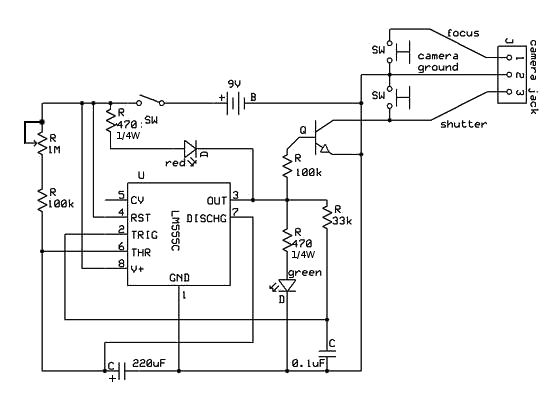
For the schematic, the circuit typically includes the following components:
1. **555 Timer IC**: The core component responsible for generating the timing signal.
2. **Resistors**: Two resistors are used to set the timing interval. The values of these resistors, along with a capacitor, determine the frequency or duration of the output pulse.
3. **Capacitor**: A capacitor is connected to the timing circuit, influencing the charge and discharge times, thus controlling the output pulse width.
4. **Transistor**: A transistor may be used to amplify the signal from the 555 timer, allowing it to drive the shutter release mechanism effectively.
5. **Diode**: A diode can be included to protect the circuit from back EMF generated by the shutter release mechanism, ensuring the longevity of the components.
6. **Power Supply**: A suitable power supply is necessary to provide the required voltage and current to the circuit.
The assembly involves connecting these components on a breadboard or a printed circuit board (PCB), ensuring proper connections according to the schematic diagram. The 555 timer's output pin is connected to the base of the transistor, which in turn is connected to the shutter release input of the camera.
This setup allows the user to trigger the camera shutter remotely, which is particularly useful for long exposure photography or situations where camera shake must be minimized. Proper calibration of the resistors and capacitor values is crucial for achieving the desired shutter timing.
In summary, the project effectively demonstrates the practical application of the 555 timer in creating a remote shutter release system, enhancing the functionality of cameras for various photographic scenarios.This instructable started with my previous camera hack making a remote shutter release. I found a 555 timer tutorial and realized how great it would b.. 🔗 External reference
Related Circuits
The circuit has been designed for telephone apparatus to indicate an incoming call as it rings using an LED for visual indication. BC550, an NPN general-purpose transistor, is utilized in the design. The circuit operates by detecting the ringing voltage...
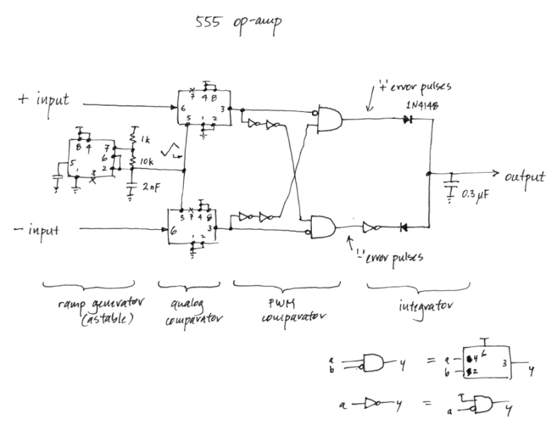
Is it feasible to create an operational amplifier using only 555 timer chips and passive components? While this may not be a practical inquiry, given the availability of low-cost and efficient op-amps, it does have some aesthetic interest. In...
is circuit was requested from an email. It will allow your car headlights to flash on and off at the same time or it will cause them to flash alternately. The circuit is based on the 555 timer. It...
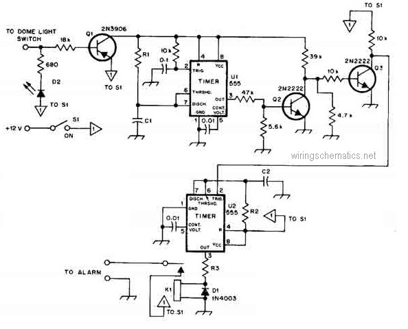
This circuit diagram represents a smart car alarm timer. This design is more advanced compared to traditional car alarm systems. When activated, the alarm remains active for 80 seconds, following an initial delay of 15 seconds. The smart car alarm...
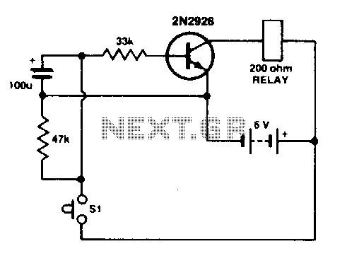
Press SI. The 100 µF electrolytic capacitor rapidly charges up from approximately 0 V. The transistor becomes forward biased, allowing collector current to flow and operate the relay. When SI is released, the capacitor discharges through the 33 K...
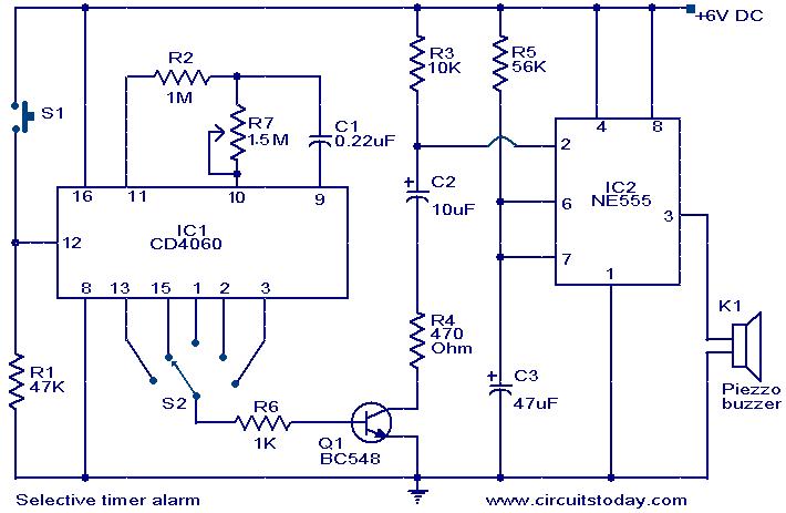
A timer circuit utilizing the IC 4060 is presented. The IC 4060 functions as a 14-stage binary counter equipped with an integrated oscillator. The components R2, R7, and C1 are responsible for determining the oscillator's frequency, causing the outputs...
Warning: include(partials/cookie-banner.php): Failed to open stream: Permission denied in /var/www/html/nextgr/view-circuit.php on line 713
Warning: include(): Failed opening 'partials/cookie-banner.php' for inclusion (include_path='.:/usr/share/php') in /var/www/html/nextgr/view-circuit.php on line 713