
Resistance and capacitance of several phase shifting trigger circuit
The unidirectional thyristor trigger circuit serves as a fundamental building block for controlling AC power in various applications, including light dimming, motor speed control, and heater regulation. The TRIAC, being a bidirectional device, allows for control in both halves of the AC waveform, making it suitable for AC loads.
The direct trigger circuits shown in Figures 16-28 (a) and (b) utilize a simple gate triggering mechanism, enabling the thyristor or TRIAC to turn on when a sufficient gate current is applied. This method is straightforward and effective for applications requiring basic on/off control.
In Figure 16-28 (c), the dual diode trigger circuit is presented, which typically employs two diodes to provide a more robust triggering mechanism, allowing for greater reliability in switching applications. This configuration can help mitigate issues related to noise and false triggering.
The inverse parallel configuration of light-emitting diodes in Figure 16-28 (d) serves as an innovative approach to triggering, where the LEDs illuminate during the triggering event, providing visual feedback. This method can enhance user interaction and monitoring in circuit applications.
Figure 16-28 (e) introduces a neon bulb trigger circuit, which leverages the unique characteristics of neon bulbs to provide a simple and effective triggering solution. Neon bulbs have a distinct firing voltage and can be used in low-power applications where visual indication is also desired.
The circuit depicted in Figure 16-28 (f) employs two NPN diodes, such as the 3DG6, to create a reliable trigger circuit. NPN diodes can provide fast switching times and are suitable for high-frequency applications, making this configuration advantageous for modern electronic designs.
In Figure 16-28 (g), the anti-parallel diode trigger circuit is illustrated, which allows for bidirectional current flow and can be particularly useful in applications where the load may change polarity.
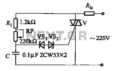
The triode diac trigger circuit shown in Figure 16-28 (h) is another effective means of controlling thyristors and TRIACs. The diac provides a sharp turn-on characteristic, which can improve the performance of the triggering mechanism in AC applications.
Finally, Figure 16-28 (i) depicts a touch reverse hair circuit utilizing two series regulators. This type of circuit can be employed in personal grooming devices, providing adjustable power settings based on user interaction. By integrating these various triggering methods, designers can create versatile and efficient control circuits tailored to specific application needs.The introduction for unidirectional thyristor trigger circuit is equally applicable to the TRIAC. Here are some also for bidirectional circuit shown in Figure 16-28. Figure 16-28 (a) and (b) is a direct trigger circuit; Figure 16-28 (c) for the dual diode to trigger the trigger circuit; Fig. 16-28 (d) for the introduction of two light-emitting diodes in inverse parallel trigger circuit; Figure 16-28 (e) for the introduction of neon bulbs trigger circuit; Figure 16-28 (f) for the introduction of two NPN diode (such as 3DG6, etc.) of the trigger circuit; Figure 16-28 (g) for the introduction of two anti-parallel diode trigger circuit; Figure 16-28 (h) for the introduction of a triode diac trigger circuit; Fig. 16-28 (1) for the introduction of two series regulator touch reverse hair circuit.
Related Circuits

This circuit features an appealing Christmas lights setup. Upon activation, the lights (HL) gradually increase in brightness. Once they reach maximum brightness, they automatically dim, and upon reaching the lowest brightness, they gradually brighten again, creating a smooth transition...

This electronic dice displays results using LEDs arranged to represent each face of a die. The circuit diagram incorporates IC 4022, which functions as a counter. The electronic dice circuit utilizes a combination of integrated circuits and discrete components to...
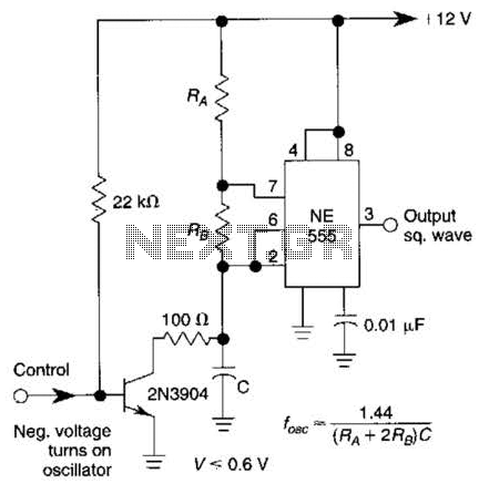
This gated 1-kHz oscillator provides a press-to-turn-on functionality, with waveforms available at the output of pin 3 and across capacitor CI. The gated 1-kHz oscillator circuit is designed to produce a square wave output that can be activated by a...

This electronic RF detector project is constructed using common transistors and a few standard electronic components. The RF detector is capable of responding to RF signals below the standard broadcast band and extending to over 500 MHz, providing both...

This time delay relay circuit is constructed using the NE/SE555 integrated circuit, manufactured by Intersil, which features a precision timer. The circuit exhibits stability against temperature variations. The NE/SE555 integrated circuit is a versatile timer used in various applications, including...

A simple digital circuit is presented that can be used to precisely control the AC power supply. This circuit does not include a digital-to-analog conversion component. In its application, effective control is established through a computer system that sends...