
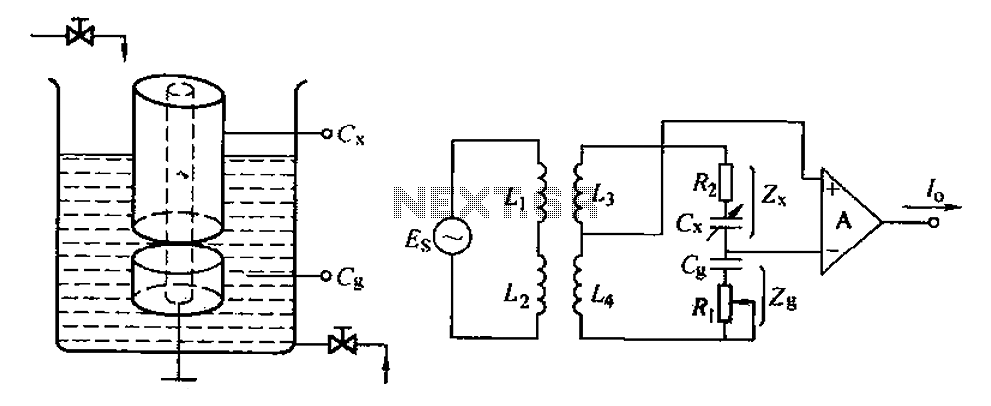
Capacitive level measuring circuit
The capacitive level meter operates under the principle of capacitance variation due to changes in the dielectric medium between the capacitor plates. The sensor typically consists of two conductive plates separated by a dielectric material, which can be air, liquid, or solid. When the level of a liquid rises, the dielectric constant of the medium between the plates alters, leading to an increase in capacitance. This change can be mathematically represented by the formula:
\[ C = \frac{εA}{d} \]
where \( C \) is the capacitance, \( ε \) is the dielectric constant of the medium, \( A \) is the area of the plates, and \( d \) is the distance between them. As the liquid level increases, the effective dielectric constant increases, resulting in a higher capacitance reading. Conversely, as the liquid level decreases, the dielectric constant reduces, leading to a lower capacitance.
The measuring circuit designed for this capacitive sensor typically includes a capacitor reference arm (G) and associated electronics that can process the changes in capacitance. This circuit can convert the capacitance value into a readable signal, suitable for display or further processing. The output signal can be analog or digital, depending on the design requirements. In practical applications, the capacitive level meter is widely used in various industries for fluid level monitoring, providing a non-invasive and reliable method for measuring liquid levels in tanks, silos, and other containers. Capacitance/C tuck bit IJ volume level change is directly converted into electrical parameters, electrical parameters and then be converted to a unified signal transmission, pr ocessing, display and so on. The electrical parameters can be divided into different: resistive, capacitive and inductive and so on, now capacitive for the introduction. We know that the most simple capacitor capacitance from the above equation by changing the t d, E or A change of approach could be made, respectively, the corresponding capacitive sensor.
Capacitive level meter consists of capacitive sensors and measuring circuit. Capacitive sensors by changing the dielectric constant E of the general principle made, FIG. 6-38a, b capacitive liquid level sensors and measuring circuits. In setting a cylindrical capacitor test solution at the plate area A and distance d is fixed, the capacitance Velvet C. The dielectric medium between the plates with dielectric constant E change. Let the liquid dielectric permittivity, Tuen constant gas is e2, general E, ez, when the liquid level rises, the total dielectric constant increases.
Thus the capacitance G increases, and vice versa, when the level drops Rang, E decreases. c, decreases. It is possible that by measuring the C rhyme change the level of liquid in the container. Figure 6-38b capacitance measuring circuit, G is the reference arm capacitance.
Related Circuits
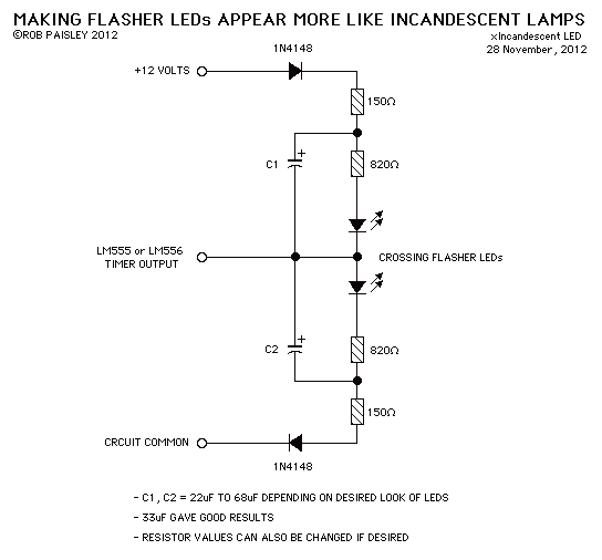
This circuit when used with a 555 timer will cause light emitting diodes to turn on and off more slowly. This will make the LEDs appear similar to incandescent lamps. The described circuit utilizes a 555 timer IC configured in...
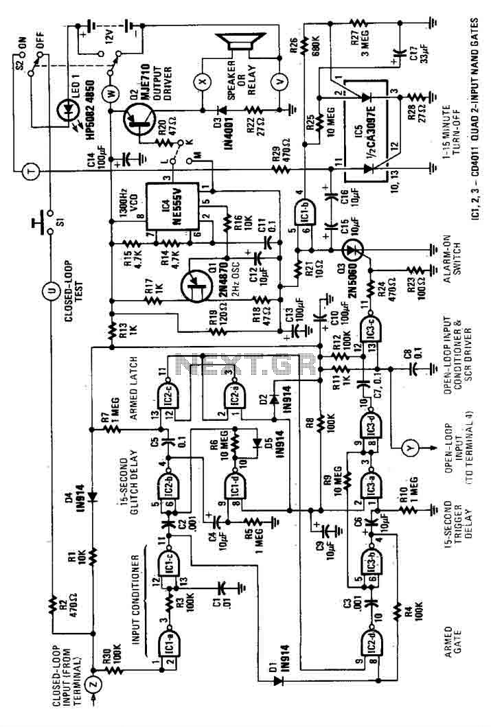
This house alarm circuit features both open and closed loop sensors and includes a self-shutdown function. The delay after triggering can be adjusted between 1 minute and 12 minutes, while the delay before triggering is set at 13 seconds....
The pulse telephone 160 168 controller circuit is depicted above. This controller can be installed either on the telephone or on the switchboard of the trunk line. It effectively prevents unauthorized dialing of numbers 160 and 168. Diodes D1...
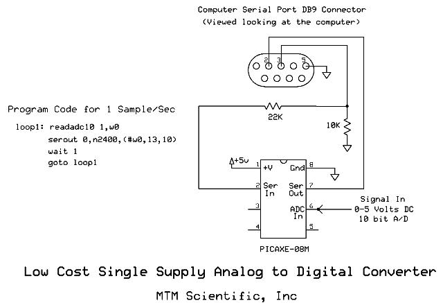
Collecting and storing experimental data presents a common challenge for hobbyists. A widely used method involves utilizing a device that converts analog data into digital format and stores the information on a computer. These devices are known as A/D...
This circuit below shows a teleremote circuit that enables the switching on and off of appliances through telephone lines. It can be used. The teleremote circuit operates by utilizing telephone lines to control electrical appliances remotely. The primary components of...

This is a low-cost FM antenna booster designed to enhance reception of programs from distant FM stations. The FM antenna booster circuit features a common-emitter tuned RF preamplifier utilizing the VHF/UHF transistor 2SC2570 (C2570). The schematic illustrates the configuration...
Warning: include(partials/cookie-banner.php): Failed to open stream: Permission denied in /var/www/html/nextgr/view-circuit.php on line 713
Warning: include(): Failed opening 'partials/cookie-banner.php' for inclusion (include_path='.:/usr/share/php') in /var/www/html/nextgr/view-circuit.php on line 713