
very simple oscillator 7700 Hz
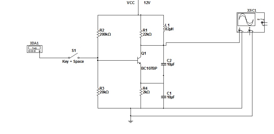
The circuit simulation involves utilizing NI Multisim, a powerful software tool designed for electronic circuit design and analysis. The primary function of the oscillator in this circuit is to produce a stable waveform, which is essential for timing applications in various electronic devices. The stability of the waveform is critical, as it ensures consistent performance in digital circuits.
In order to save the simulation results, users must access the source code within the Multisim environment. This feature allows for the documentation and reuse of circuit designs and simulation data, which is particularly beneficial for iterative design processes or educational purposes.
The choice of clock source is a fundamental aspect of circuit design. Different devices may require specific types of clock sources, such as crystal oscillators, RC oscillators, or PLLs (Phase-Locked Loops), depending on the frequency stability and accuracy needed for the application. Understanding the characteristics and limitations of these clock sources is vital for optimizing circuit performance and ensuring compatibility with other components in the system.
In conclusion, the successful simulation of the circuit in NI Multisim version 11 hinges on understanding the oscillator's role in generating stable waveforms and the importance of selecting the appropriate clock source for the specific application.for simulation this circuit you must have NI multisim produced by National Instrument When oscillator nearing stable Waveform oscillator if you want save file go to source code and you need multisim ver11 How its work exactly? you must know this fact , most device have clock source ,and clock source they used depend. 🔗 External reference
Related Circuits
The preamp featured has optional tone and balance controls which may be omitted if desired. The input switching may be extended if needed to accommodate more signal sources. In this version, no RIAA (phono) input is provided. See the...
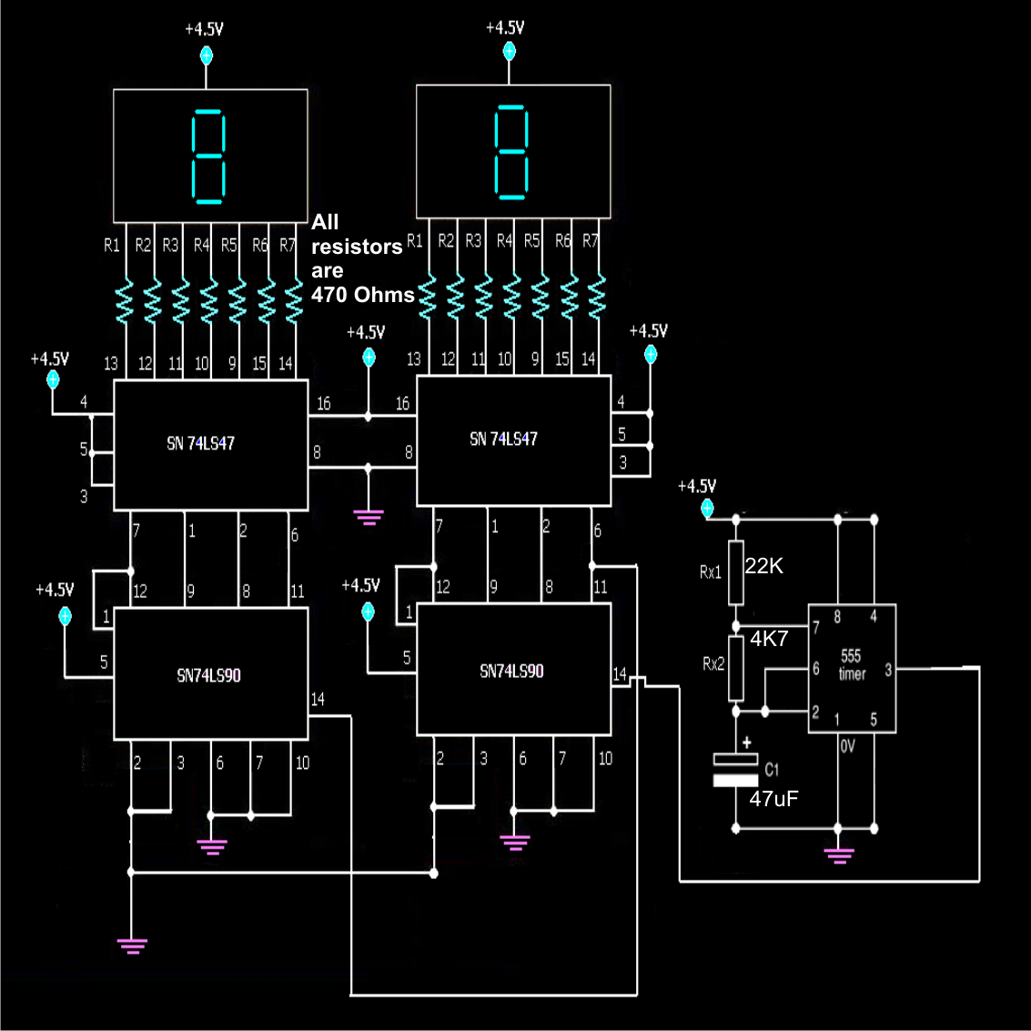
A simple frequency counter circuit can be easily constructed by any electronics enthusiast for its intended purpose. The circuit diagram was provided by Mr. Kapital through an order on Fiverr. The functioning of the circuit involves generating positive voltage...
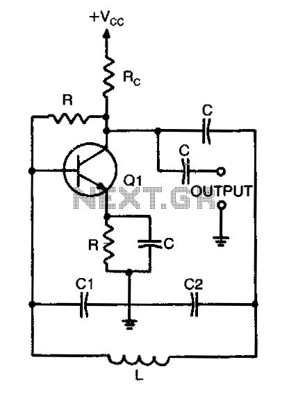
When calculating the resonant frequency, use the formula C1C2/(C1+C2) for the total capacitance of the L-C circuit. In an L-C (inductor-capacitor) circuit, the resonant frequency is a critical parameter that determines the frequency at which the circuit will oscillate. The...
These circuits provide overvoltage protection in the event of a voltage regulator failure or the application of an external voltage. They are intended for use with a power supply that incorporates some form of short circuit protection, such as...
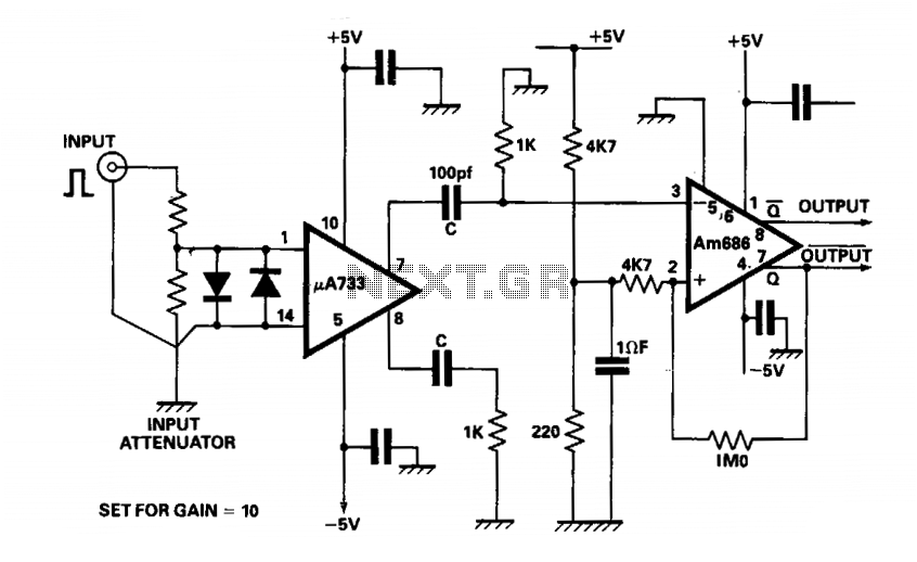
The output of a video amplifier is differentiated before being fed to a Schottky comparator. The propagation delay is typically reduced to 10 ns. The output pulse width is determined by the value of C, 10 pF, resulting in...
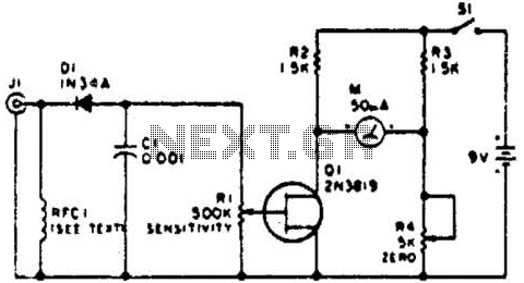
This circuit employs a FET as a DC amplifier within a bridge configuration. Resistor R4 is adjusted for meter nulling with switch J1 short-circuited. Any surplus 50-mA meter can be utilized in this circuit. RFC1 represents a suitable RF...