
Wien-Bridge Oscillator

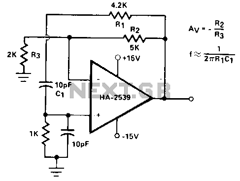
The HA2541 oscillator circuit operates by utilizing a combination of resistive and capacitive components to generate and stabilize oscillations. The primary function of the HA2541 is to produce a sine wave output, and its design allows it to achieve frequencies up to 50 MHz effectively.
The circuit includes a feedback network formed by R1, C1, R2, and C2, which is critical for establishing the oscillation condition. The feedback network must provide a gain slightly above three to sustain oscillation. The gain is adjusted using the resistors R8 and R9, which fine-tune the feedback loop.
The diode limiting provided by D1 and D2, along with resistors R3 to R7, helps to shape the waveform, ensuring that the output remains within desired amplitude levels and prevents distortion. This diode limiting is essential for maintaining the integrity of the sine wave output, especially at higher frequencies.
The choice of components, particularly the values of R1, C1, R2, C2, R8, and R9, directly affects the frequency stability and quality of the output waveform. It is crucial to select these components carefully to optimize performance and achieve the desired frequency response.
Overall, the HA2541 oscillator circuit is a robust design suitable for applications requiring high-frequency sine wave generation, leveraging the capabilities of the HA2541 operational amplifier in conjunction with passive components to achieve reliable and stable oscillation. The HA2541 is well-suited for use as the heart of an oscillator. In spite of the rudimentary diode limiting that is provided by R3 through R7 and D1 and D2, a good-quality sine wave of 40 MHz is readily attainable with an upper limit of 50 MHz, which exceeds the unity-gain bandwidth of HA-2541. Rl/Cl and R2/C2 provide the required regenerative feedback needed for adequate frequency stability. In theory, the feedback network requires a gain of three to sustain oscillation. However, the practical gain needed is just over three and is provided by R8 and R9.
Related Circuits
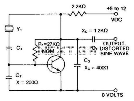
A capacitor in series with the crystal can be utilized to adjust the output frequency of the oscillator. The value can range between 20 pF and 0.01 µF, or it can be a trimmer capacitor. The values are approximate...
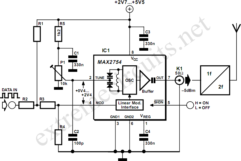
High-frequency voltage-controlled oscillators (VCOs) are challenging to construct. Maxim has developed an integrated 1.2 GHz oscillator, the MAX2754. The center frequency is adjustable via the TUNE input, while a linear modulation input enables frequency modulation. This integrated circuit (IC)...
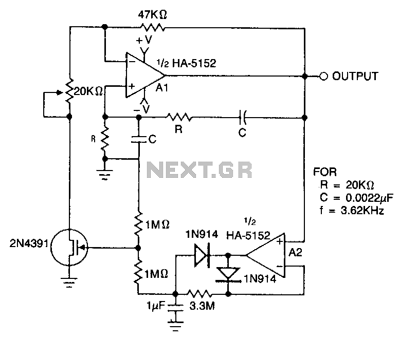
This circuit employs an HA-5152 dual operational amplifier and a field-effect transistor (FET) to create a low-voltage, low-power Wien bridge sine-wave oscillator. The frequency of oscillation is controlled by resistors and capacitors, while the FET functions as a voltage-controlled...
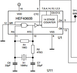
The initial issue pertains to the 16 MHz crystal oscillator, which fails to initiate oscillation. However, when substituting the 16 MHz crystal with an 11 MHz or lower frequency crystal, the oscillator functions correctly. An oscilloscope reveals a clear...
Intended primarily as a building block for a QRI transmitter, this 20-MHz oscillator delivers a clean 6-V peak-to-peak signal into a 100-ohm load. The 20-MHz oscillator functions as a critical component in the design of a QRI transmitter, providing a...
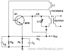
An Armstrong Oscillator is a type of oscillator that utilizes a tickler coil to provide feedback from the tank circuit. This oscillator generates a sine-wave output with constant amplitude and fairly constant frequency within the RF range. Inductor L1...