
Car Alarm Simulator

The car alarm simulator circuit operates by utilizing the voltage produced by the vehicle's alternator. When the car engine is running, the alternator generates a higher voltage, typically around 13.8 to 14.4 volts, compared to the resting voltage of approximately 12 volts when the engine is off. This voltage difference can be harnessed to activate an LED, providing a visual indication of the car's operational status.
The core components of the circuit include a voltage comparator, an LED, and resistors for current limiting. The voltage comparator is configured to compare the voltage levels from the vehicle's battery and alternator. When the engine is off, the comparator detects a lower voltage and keeps the LED turned off. Conversely, when the engine is started, the increased voltage from the alternator triggers the comparator, which then allows current to flow through the LED, illuminating it to signal that the car is running.
In terms of construction, the circuit can be built on a breadboard or a printed circuit board (PCB) for a more permanent solution. The LED should be chosen based on the desired brightness and visibility, while the resistors must be calculated to ensure that the LED receives the appropriate current without exceeding its maximum ratings. Additional features, such as a buzzer or additional LEDs for different statuses, can be incorporated for enhanced functionality.
Overall, this car alarm simulator circuit serves as a useful tool for vehicle owners to easily monitor their car's engine status, providing both educational and practical applications in automotive electronics.This is a car alarm simulator which using the LED as a simulation output. This simple circuit can tell you whether your car is running or not by detecting the voltage difference when the car is on and off. This occurs because when your car This is a car alarm simulator which using the LED as a simulation output.
This simple circuit can tel l you whether your car is running or not by detecting the voltage difference when the car is on and off. This occurs because when your car is running the Alternator puts a out a voltage a little bit higher than when the car is off.
This circuit actually is a kits, you can get the kits at But it is very possible to you to build your own car alarm simulator circuit. 🔗 External reference
Related Circuits
The following two-transistor circuit is a preamplifier for magnetic phono cartridges, characterized by its frequency response defined by the RIAA standard for phono recording. This preamp circuit has a gain of approximately 40 dB (midband) at 1 kHz. The...
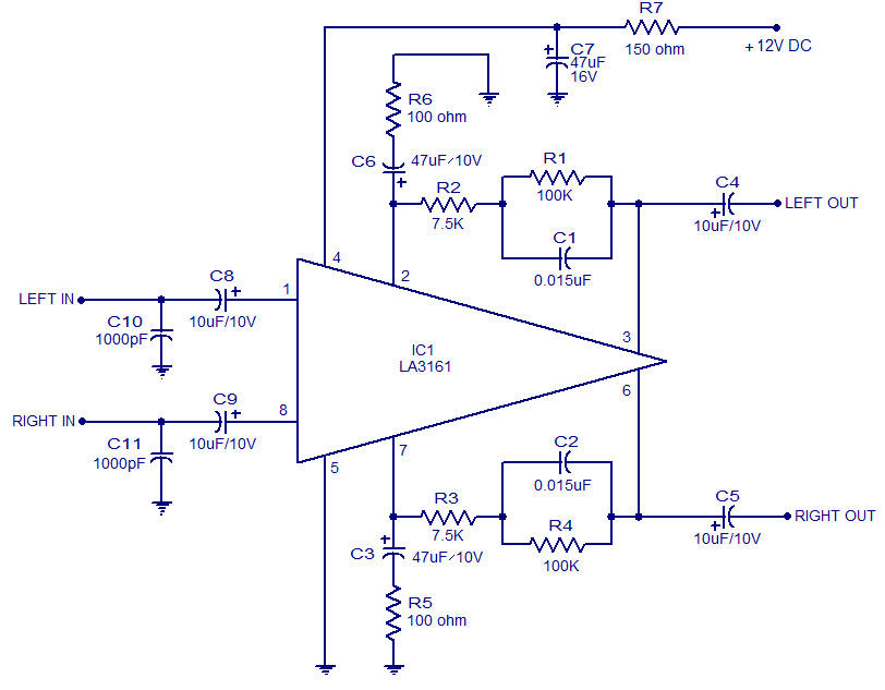
The LA3161 is an integrated two-channel preamplifier designed for car stereo applications. It operates on a 12V DC power supply. The LA3161 preamplifier is specifically engineered to enhance audio signals in automotive environments, ensuring optimal sound quality for car stereo...
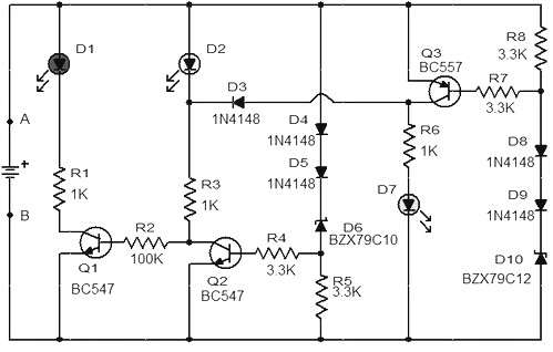
When the battery voltage is 11.5V or less, transistor Q1 is activated, and LED D1 will illuminate. When the battery voltage is between 11.5V and 13.5V, transistor Q2 is activated, causing LED D2 to light up. At a battery...
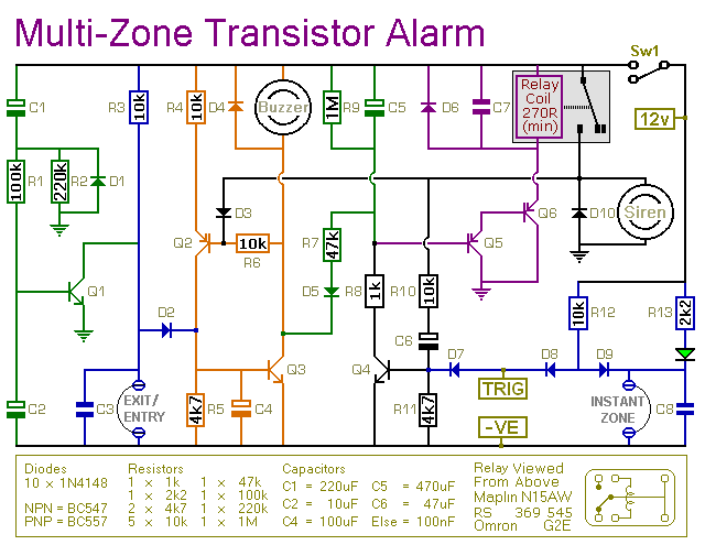
This transistor-based alarm features automatic exit and entry delays, along with a timed bell cut-off and system reset. In addition to the exit/entry zone, the basic alarm board includes one instant zone, which is sufficient for many applications. However,...
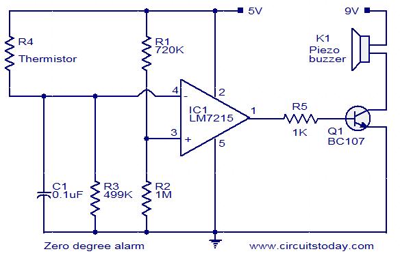
This circuit is designed to trigger an alarm when the temperature drops below zero degrees Celsius. A thermistor is utilized to measure the temperature. The operational amplifier LM7215 is employed to compare the reference voltage with the voltage from...
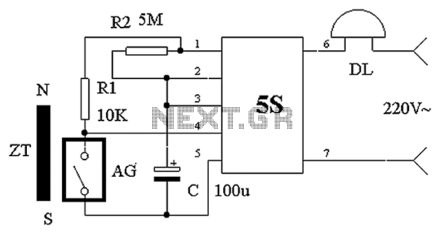
The circuit operates based on the principle of a shaped permanent magnet mounted on the door, referred to as ZT, and a normally closed reed switch, labeled AG, mounted on the door frame. Under normal conditions, ZT is in...
Warning: include(partials/cookie-banner.php): Failed to open stream: Permission denied in /var/www/html/nextgr/view-circuit.php on line 713
Warning: include(): Failed opening 'partials/cookie-banner.php' for inclusion (include_path='.:/usr/share/php') in /var/www/html/nextgr/view-circuit.php on line 713