motion detector sensor circuit
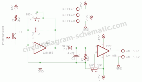
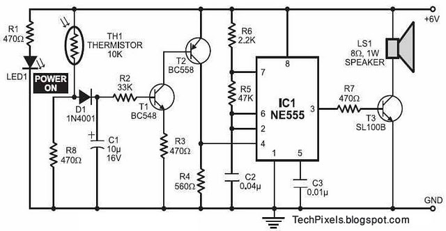
This circuit is a motion detection sensor that utilizes a light source and detector as an infrared motion detector. The motion sensor employs an infrared LED and a phototransistor. Since it relies on light, the sensor's sensitivity can be influenced by environmental disturbances such as wind, debris, or stray light. The schematic is divided into two sections: the transmitter and the receiver. The transmitter circuit is controlled by an NE555 timer configured as an astable multivibrator. An infrared LED is connected to the output of this schematic, generating a frequency of 5 kHz. In the receiver circuit, the infrared light emitted by the LED is captured by the phototransistor. Under normal conditions, when no motion is detected, the output of the LM1458 on pin 7 will be low (0 volts). Conversely, if motion is detected, the output of the LM1458 IC on pin 7 will be high (5 volts). The output from the LM1458 can be connected to a speaker, buzzer, or alarm. A PCB (printed circuit board) layout of the motion detector sensor circuit is also available for download.
The motion detection sensor circuit is designed to detect movement through the use of infrared light. The system consists of two primary components: the transmitter and the receiver. The transmitter section features an NE555 timer configured in an astable mode, which generates a continuous square wave signal at a frequency of approximately 5 kHz. This signal is used to modulate the infrared LED, which emits infrared light pulses into the surrounding environment.
The receiver section of the circuit includes a phototransistor that is sensitive to the infrared light emitted by the transmitter. When the infrared light is unobstructed, the phototransistor remains in a low conduction state, resulting in a low output voltage at pin 7 of the LM1458 operational amplifier. However, when an object interrupts the infrared light path, the phototransistor detects a change in light intensity, causing the LM1458 to switch to a high output state (5 volts).
This change in output can be utilized to trigger various alert mechanisms such as a buzzer, speaker, or alarm system, thereby providing an indication of motion detection. The LM1458 operational amplifier is chosen for its dual-channel capability, allowing for additional functionalities or processing if required.
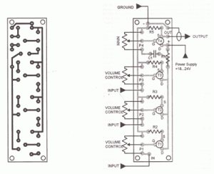
The printed circuit board (PCB) layout of the motion detection sensor circuit is designed for compactness and ease of assembly, ensuring that all components are appropriately placed to minimize interference and optimize performance. The layout typically includes pads for the NE555 timer, infrared LED, phototransistor, LM1458, and any additional components such as resistors and capacitors necessary for the circuit's operation. This PCB design can be downloaded for practical implementation.This circuit is a motion detection sensor, this circuit uses a light source and detector as a sensor infrared motion detector. Motion sensor using infrared LED and phototransistor. Because it uses light to the sensor sensitivity can be affected by environmental disturbances, such as wind, waste, or stray light.
In this schematic is divided into t wo schematic transmitter and receiver. Transmitter circuit is controlled by the NE555. NE555 astable multivibrator configuration installed. Infrared LED mounted on the output of a schematic and generate a frequency of 5 kHz. Here is a schematic drawing of motion detection sensor transmitter: At the receiver circuit of the LED infrared light captured by the phototransistor. At normal conditions ie when the sensor does not detect motion, LM1458 output on pin 7 will be value low (0 volts).
if the sensor detects movement, the LM1458 IC output on pin 7 will be value high (5 volts). IC LM1458 output can be connected with a speaker, buzzer or alarm. Here I also include a PCB (printed circuit board) of the motion detector sensor circuit and you can also download it. 🔗 External reference
